

Blog Archive
Arm Parts and Welding
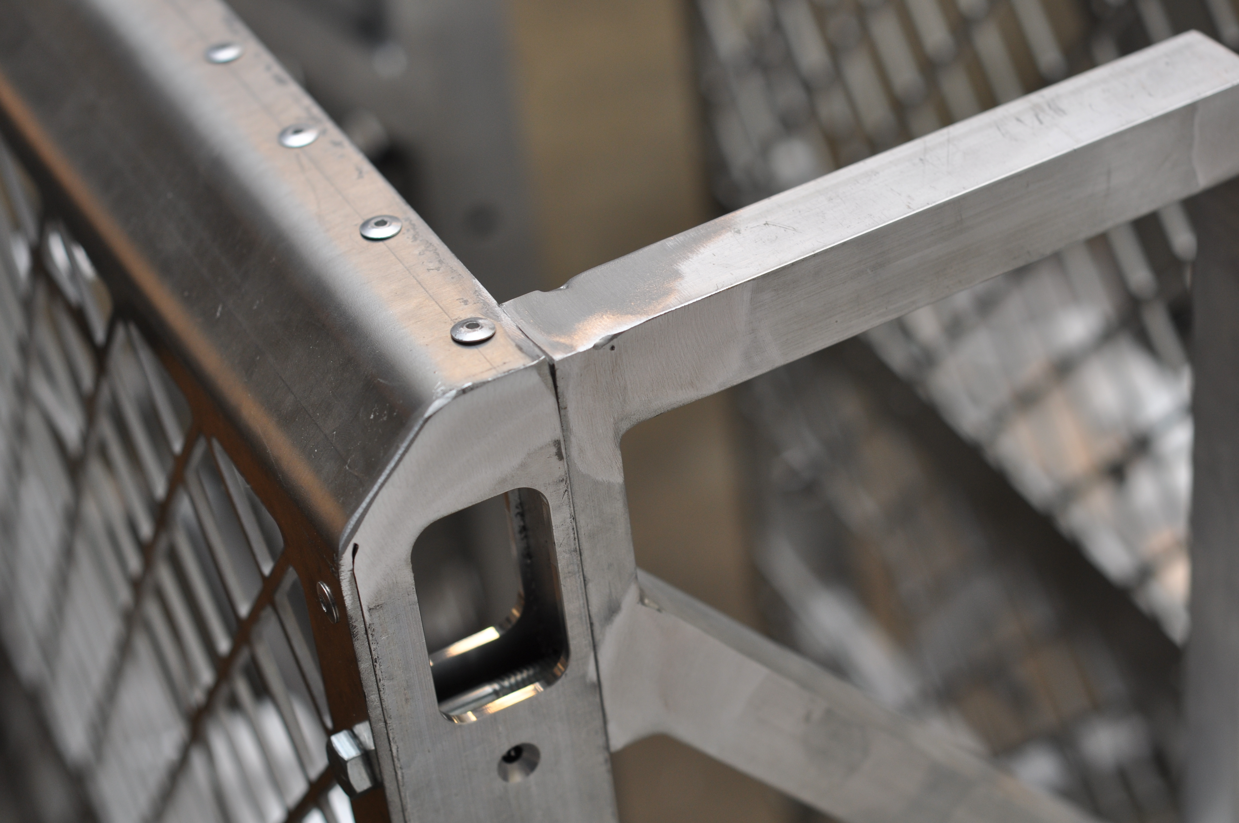
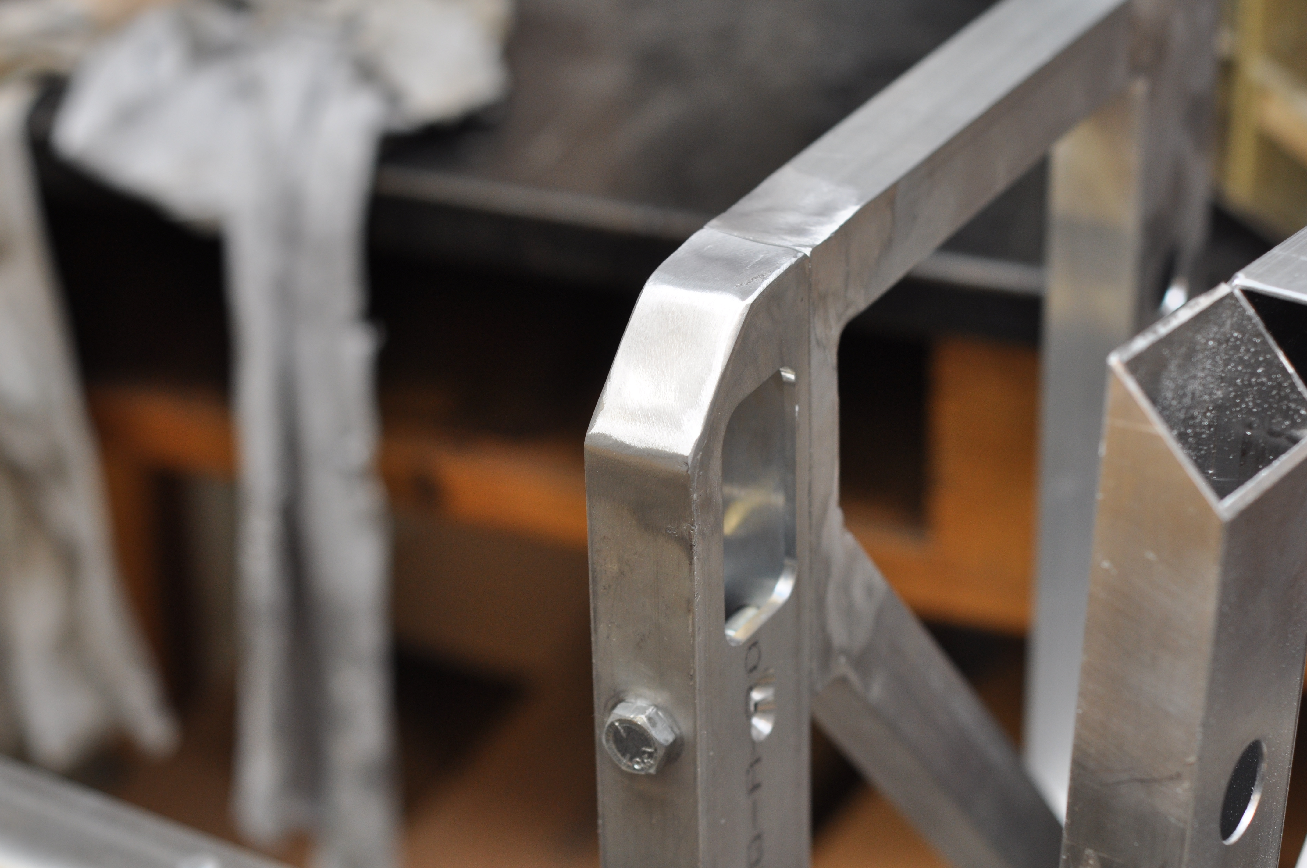
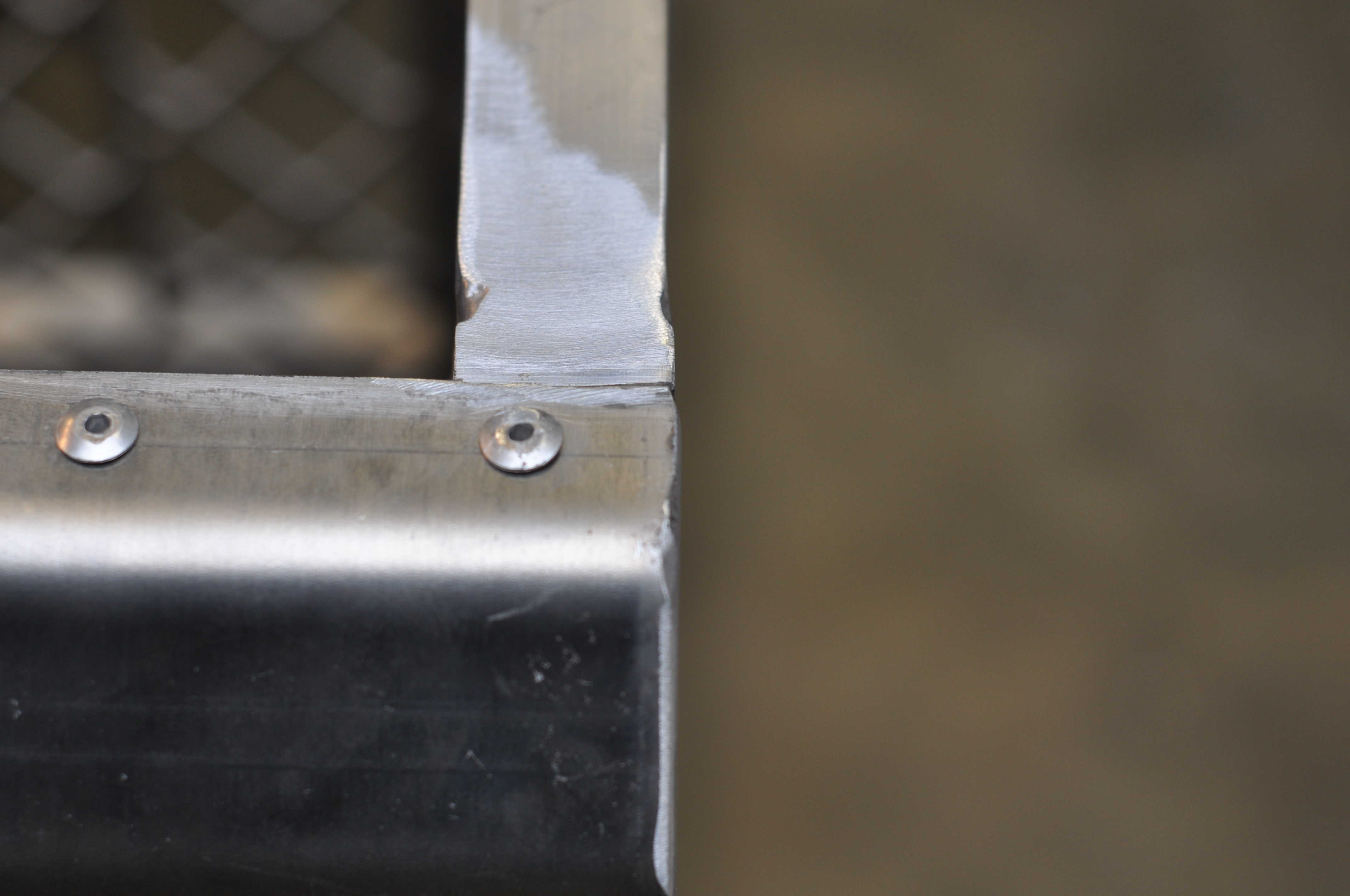
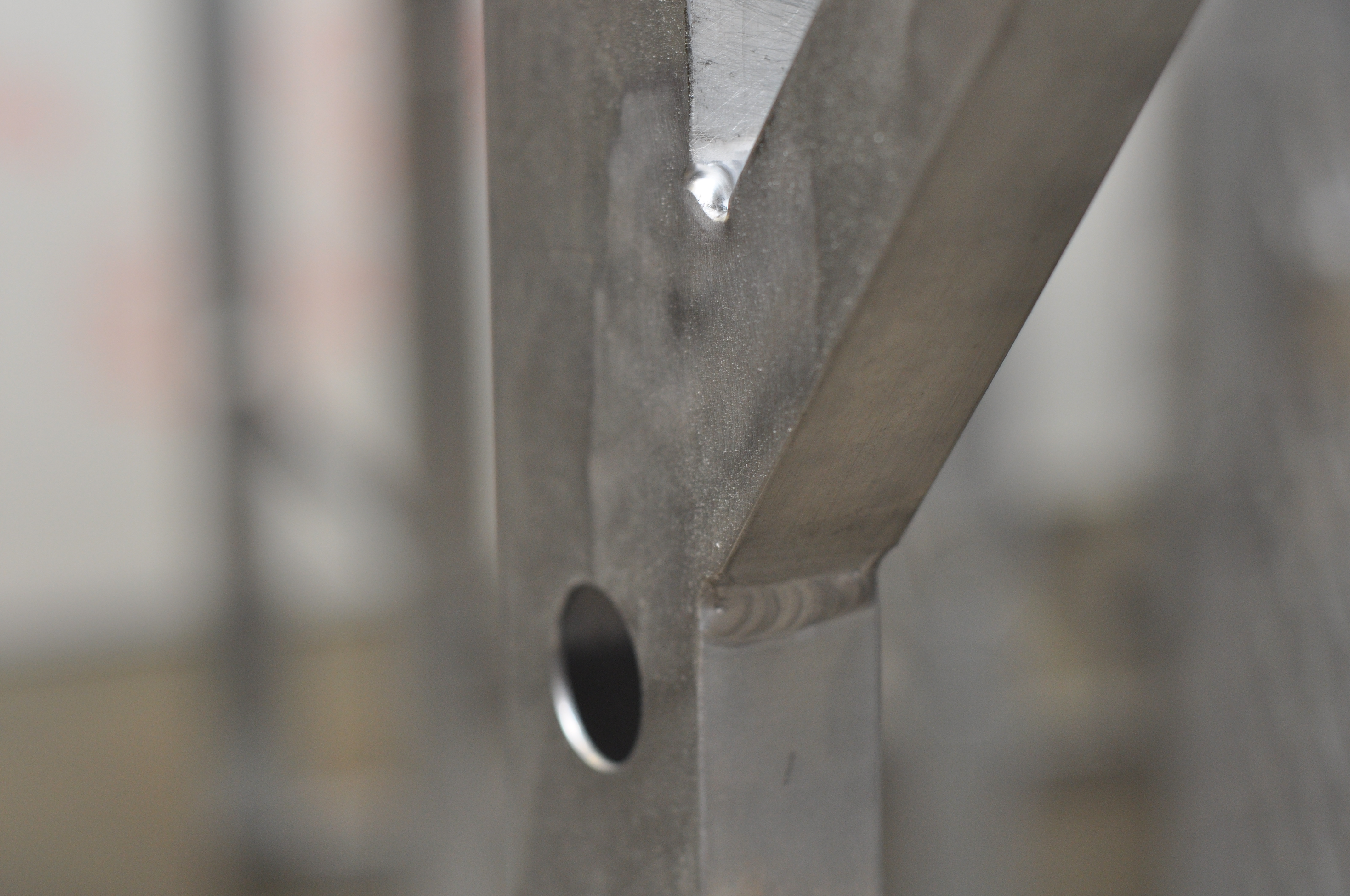
After an all-night machining marathon last night, the arm parts were completed to be welded today. Our generous supporter Foes Racing was able to align and tack weld all the pieces into place this evening. Foes did the welding for the launcher and top arm in 2008 also. Below are some quick snapshots of the parts just before leaving Foes for the evening. The arm parts will be welded tomorrow night. Please take a close look at how everything is assembled, and quickly bring it to our attention if anything seems incorrect.

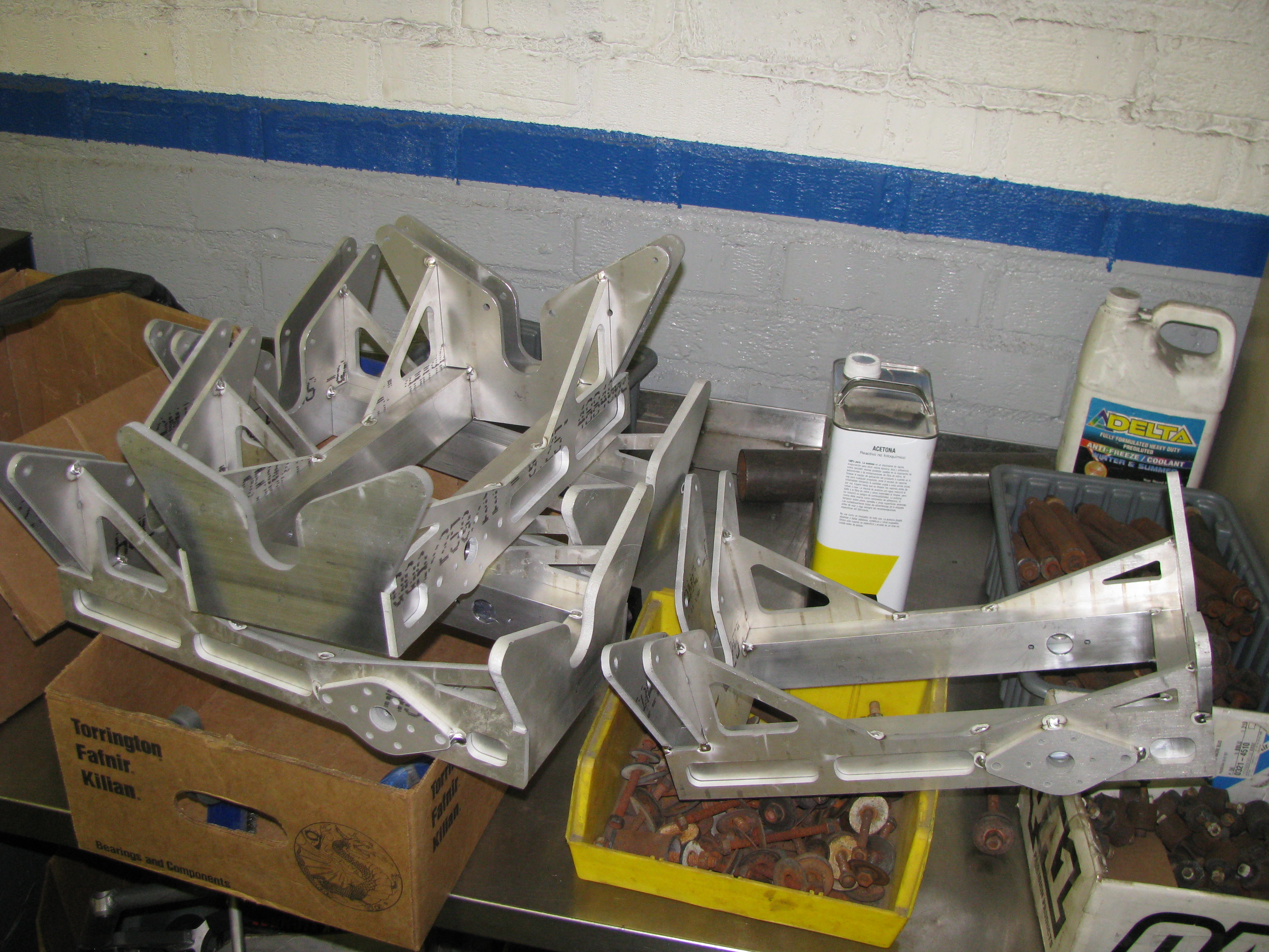
Efforts were made to align holes in waterjetted pieces with holes in the box tube pieces, and to ensure squareness during the tack-welding process. After welding is complete, a 0.875 reamer and a 1.250 reamer will be needed to enlarge the holes in the waterjetted pieces. Additionally, all threaded holes still need to be drilled and tapped.
Field Parts Have Arrived!
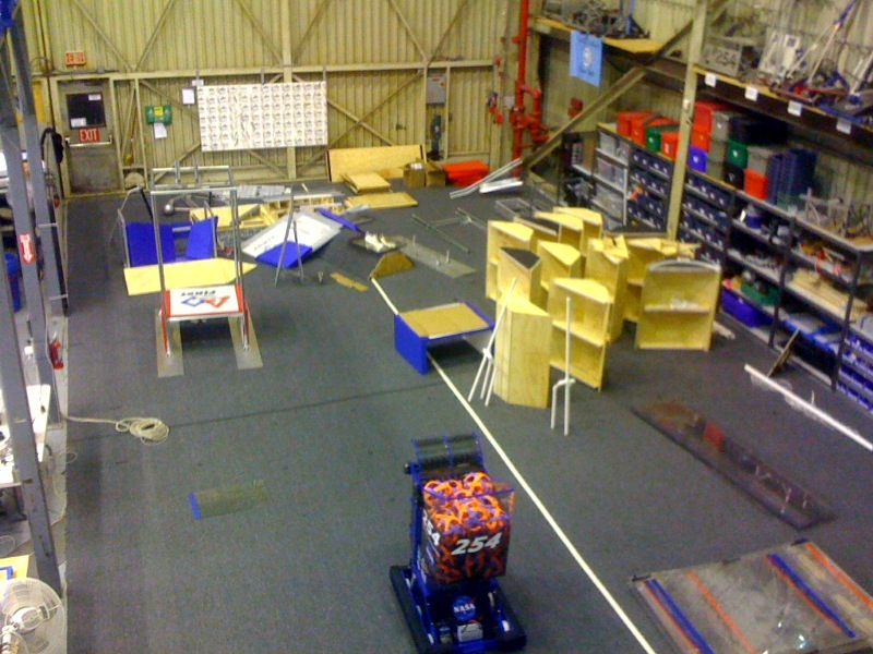
The official FIRST field components arrived today and were taken inside to be inventoried (and played with).
Field setup will begin in the next few days, as soon as we determine which building we will be setting it up in. If you get the chance, please thank Mark Leon and NASA for their generosity and support in getting us these field components. Please remember; we were lucky enough to receive these field components with the understanding that we would open our lab up and invite the other Bay Area teams to utilize it whenever possible. Let’s make sure we are gracious and welcoming hosts when they arrive, and that we fully understand how lucky we are to have the opportunity to help everyone out. We also need to take care of these components and keep them nice, as we can expect to use them at all of the local scrimmages and events that require a full sized field.
Manufacturing & Design Progress
MANUFACTURING
The manufacturing team has been working hard to produce a myriad of parts. The CNC has been running to finish the Dogs and start on parts for the Kicker. The lathe has been working to produce all of the shafts and spacers needed in the kicker.
DESIGN
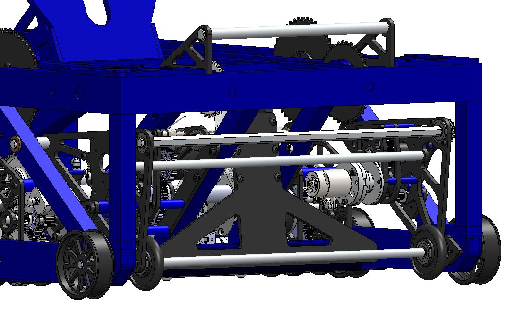
The design team has been working hard to design the roller system, the final major robot system to be designed. The plates will be sent out for waterjet cutting at BAE systems tomorrow. The CAD predicts the robot weight at about 110 lbs, but does not include certain items such as pneumatic tubing, fittings and all wiring.
Control Board Progress
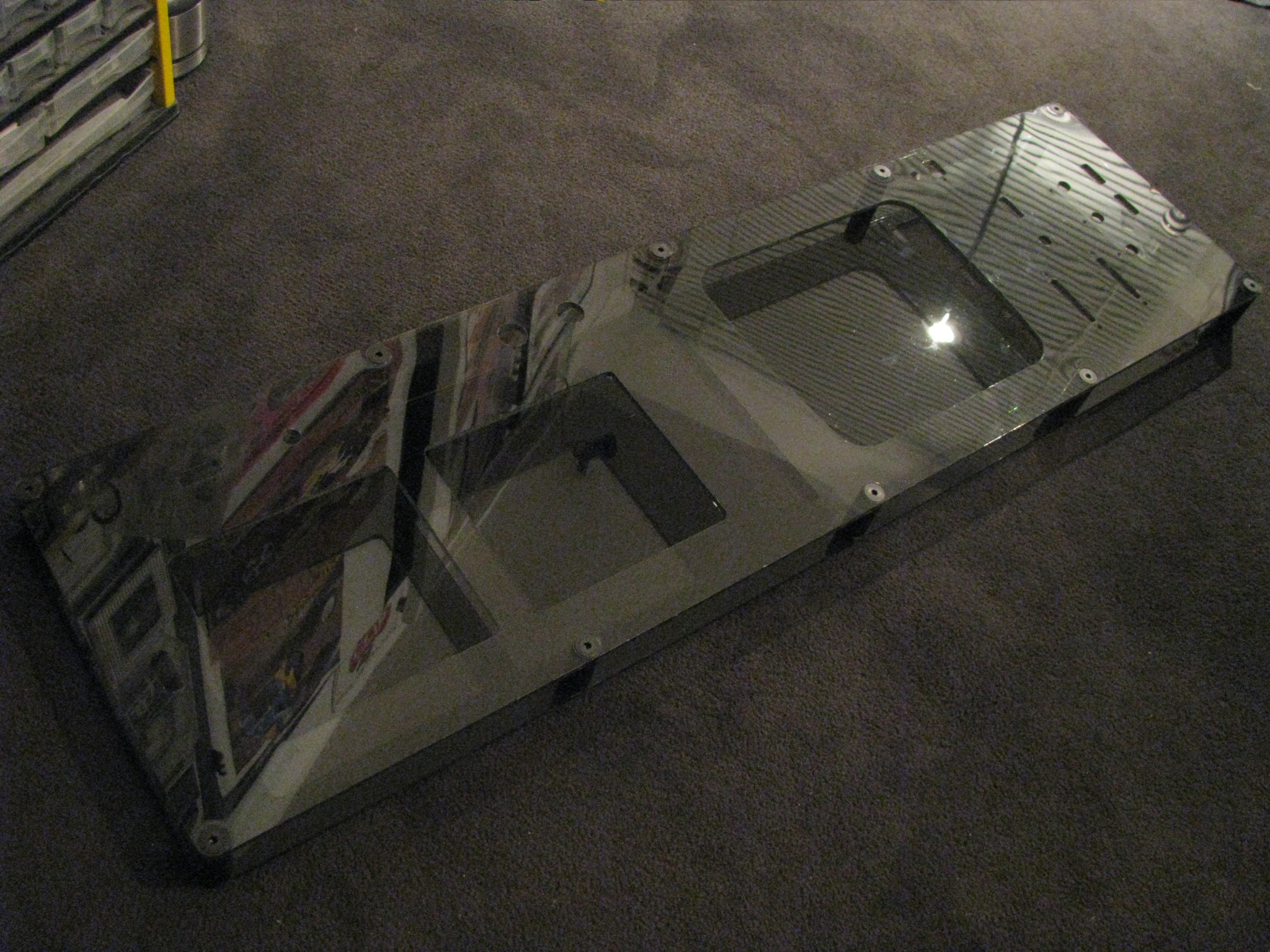
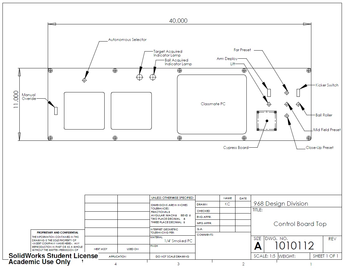
Today we were able to cut out the polycarbonate for a control board on the CNC router at Glendale Community College. It took much longer than expected, due to the polycarb melting at any feed rate over 18 IPM, even with a constant cool air blast on the endmill. Machine setup took about 75 minutes, and fixturing, cutting, and removing the panels took about an hour. Tomorrow evening we will finish cutting the second board. Below is a picture of the assembled control board.
Weekend Progress: Update
The manufacturing department was very understaffed today due to the superbowl(I guess?)
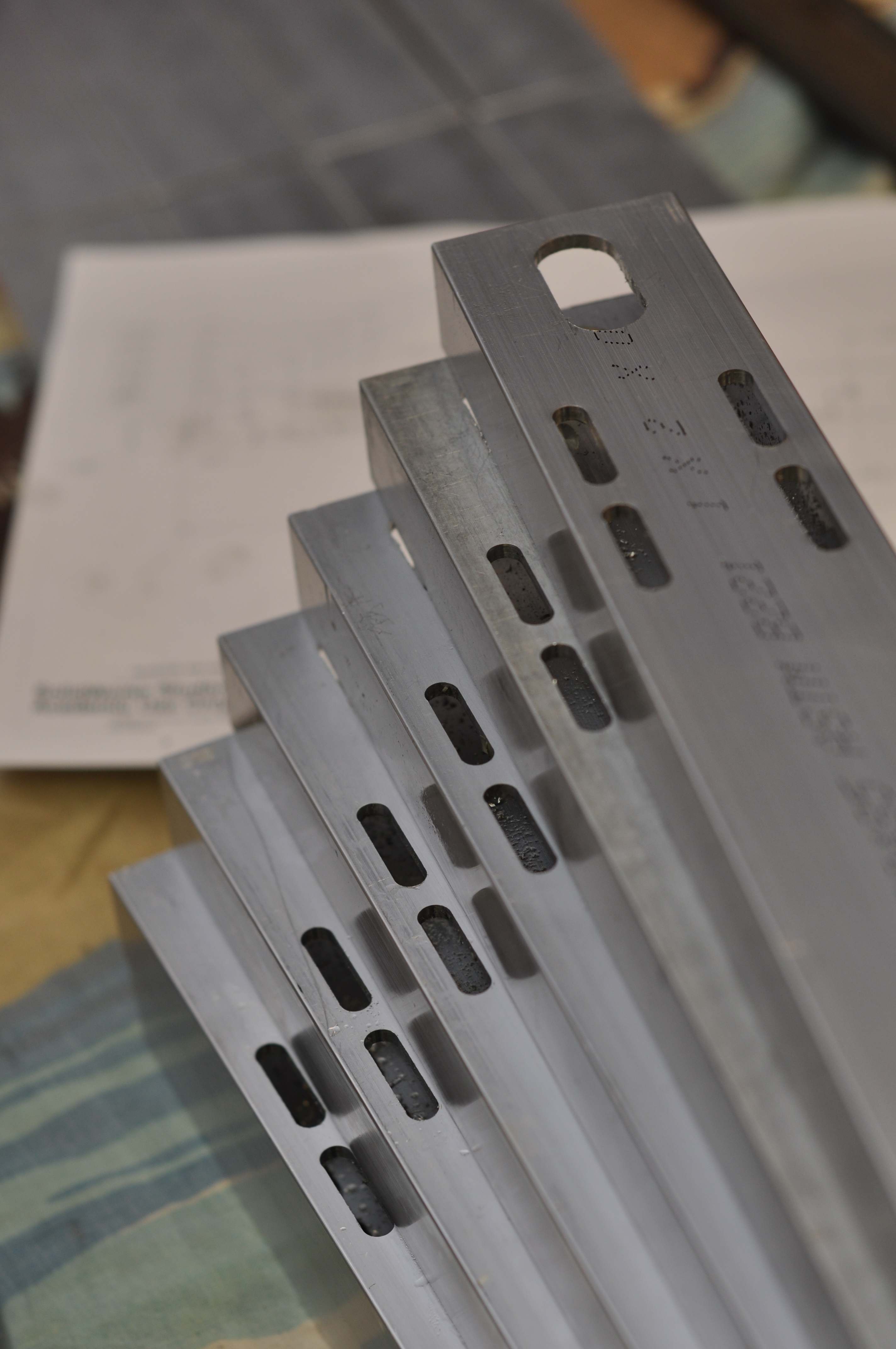
We’ve completed the milled slots on the 1 x 2 Arm sides(1010084)
Weekend Progress
Manufacturing:
Tonight we completed the four piston bearing blocks (1010073) for the kicker winch. These took much longer than anticipated using manual machines. Below is a picture of the completed parts:

For the small piston bearing blocks (1010019) we hope to have a CNC lathe available tomorrow evening. Tomorrow we hope to cut out the control boards as well, on a CNC router.
The 1 x 2 x.125 box tube parts for the arm structure have been cut, and are currently undergoing milling and drilling operations, and preparation for welding this week.
We have robots.
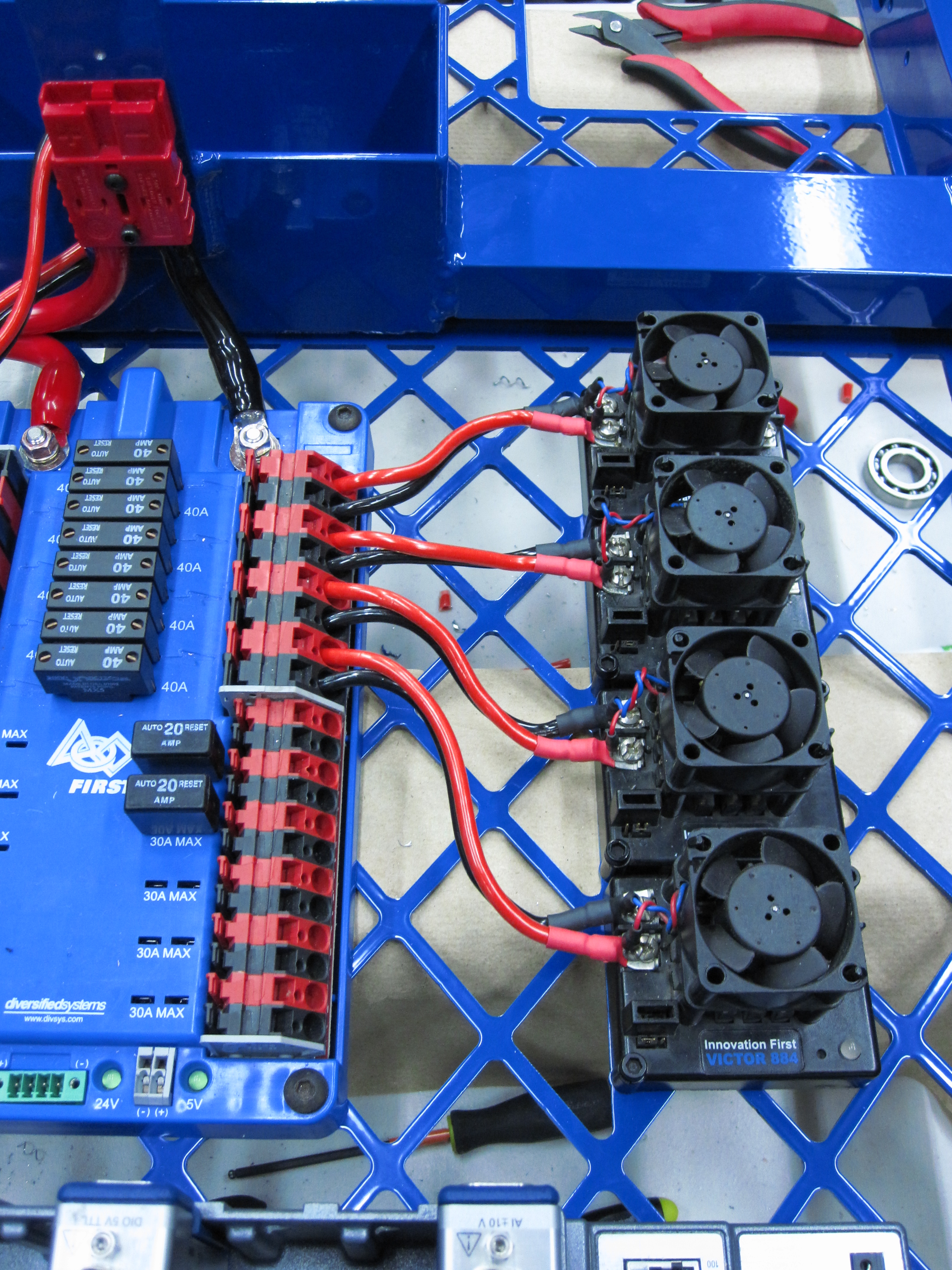
After receiving our frames very late last night, we began wiring today. We mounted all of the electronics and ran the 4 gauge primary power wires.

We then proceeded to run wires for the Victor 884 speed controllers. After several separate configurations, the most popular involves running each Victor power wire independently and not zip-tying them together at all.
Besides working on the frames, the manufacturing department continued to lathe a myriad of spacers and standoffs for the kicker and drive gearboxes. The CNC was working hard all day to cut dog ridges into our two separate dog gears and the dog lock plate.
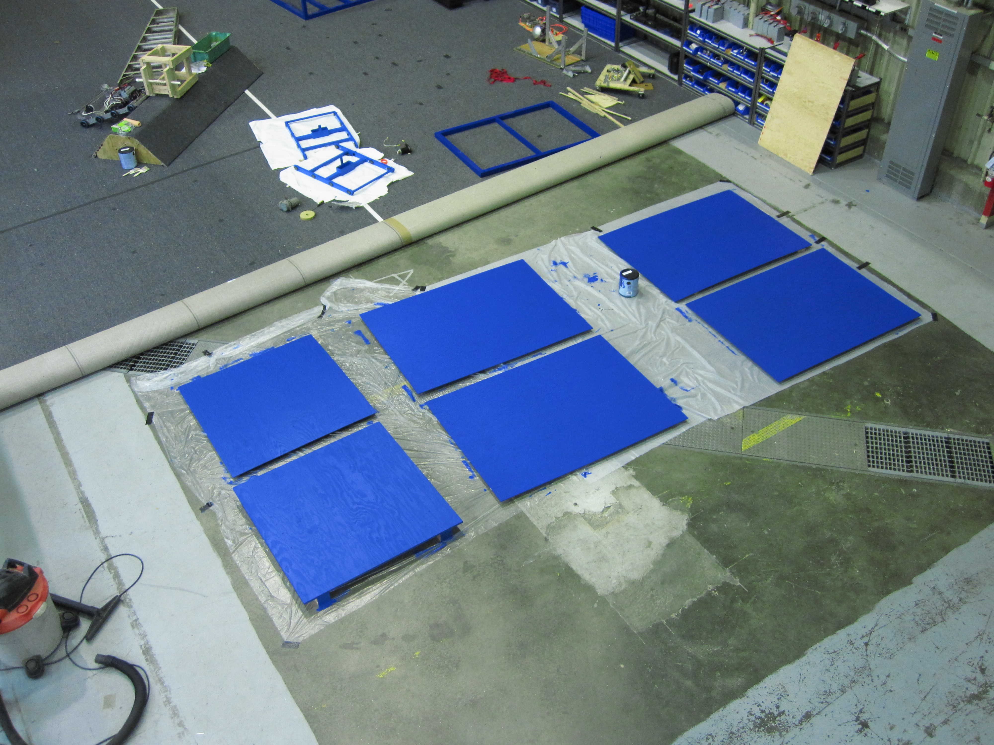
A large group of students also worked hard all day on 254’s crate, ending with painting it.
Bumper Mounting and Control Board Parts
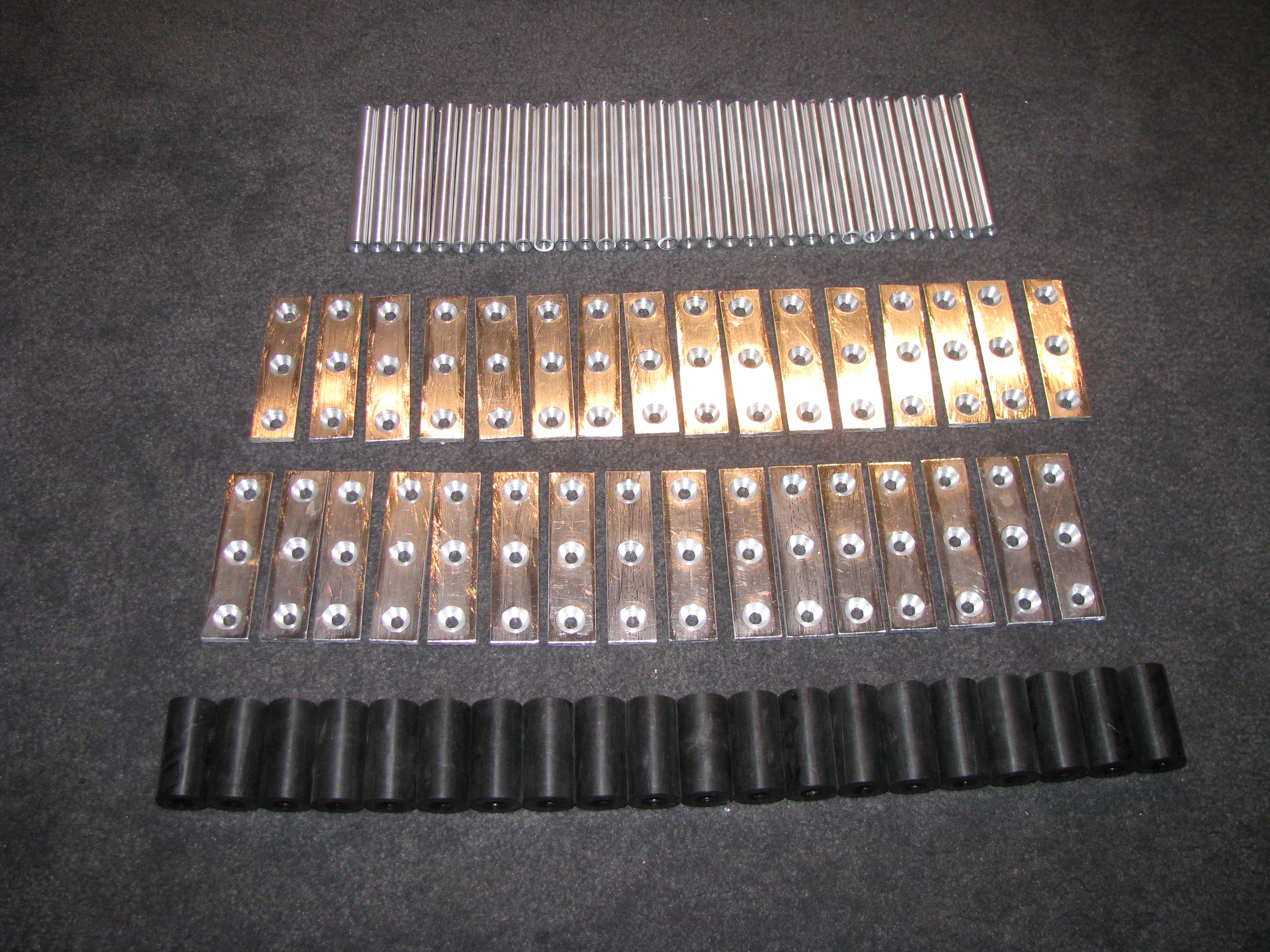
Today we completed the 32 bumper mounting pins and brackets, and 20 control board spacers. The bumper mounting scheme is nearly identical to the 968 2009 bumpers. The finished parts are shown below.
Next, we hope to cut the control board polycarbonate on a CNC router, and machine the piston bearing blocks (cones) on a CNC lathe. Additionally, we will be cutting the 1×2 box tube parts needed for the arms.
Closer to Completion
Design: The team has finalized CAD designs for our kicking device and has finalized all mechanisms.
Parts: A set of manufactured parts has been sent to our sister team, 968.
Manufacturing: We are continuing manufacture of dogs for our kicker shaft.
Design: T-shirt designs finalized!
In short, 254 is well on its way to finishing the robot (name TBD)
Finished Parts
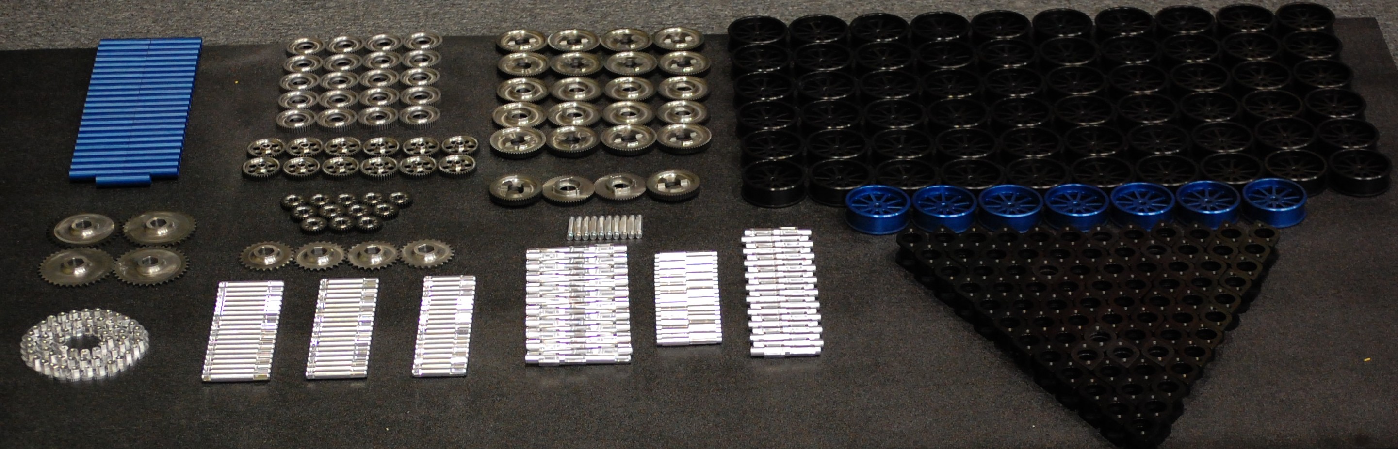
Here’s a picture of everything completed so far (Minus gearbox plates and sprockets, which are out to anodize, and frames).
We haz powdercoat.
We haz powdercoat.
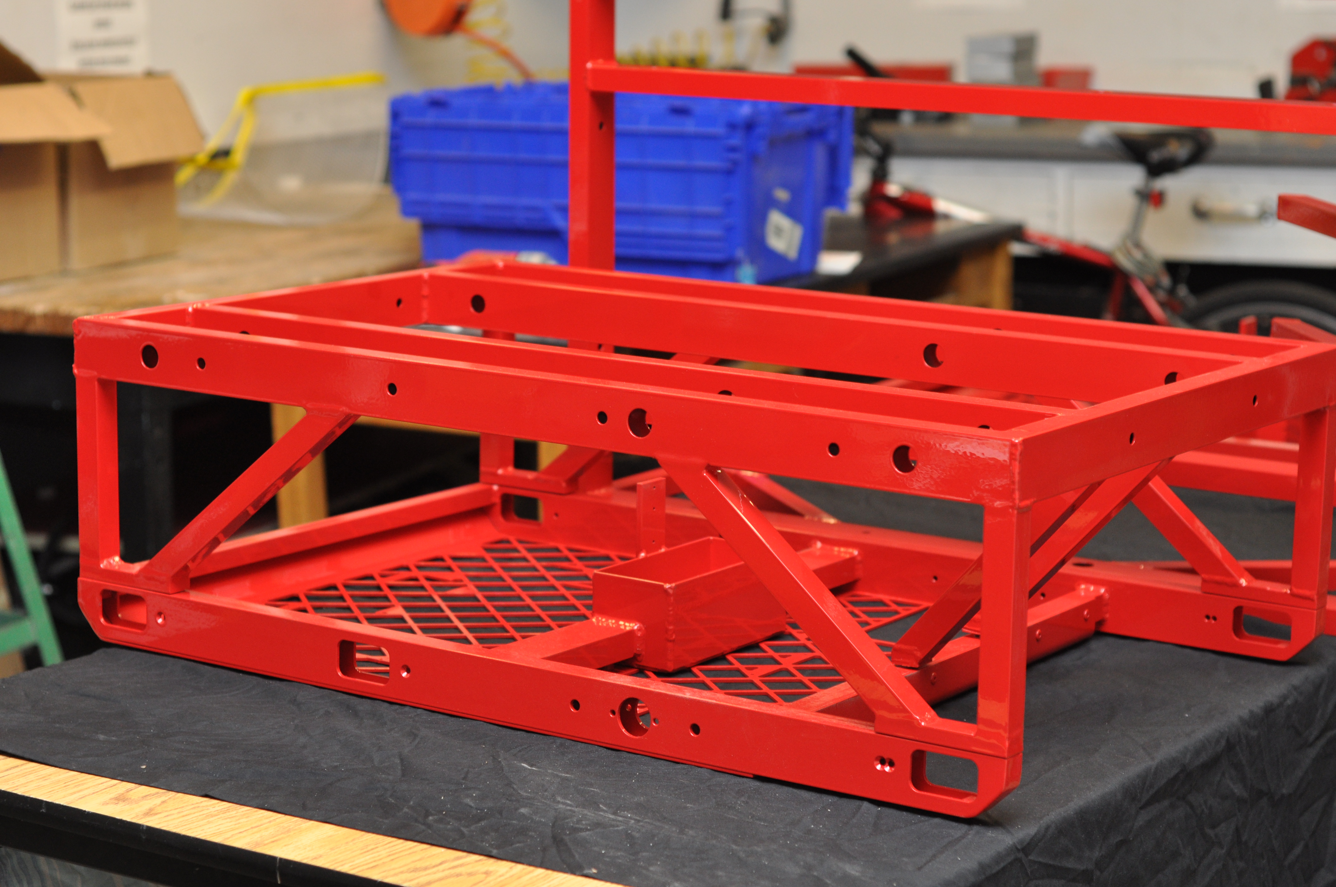

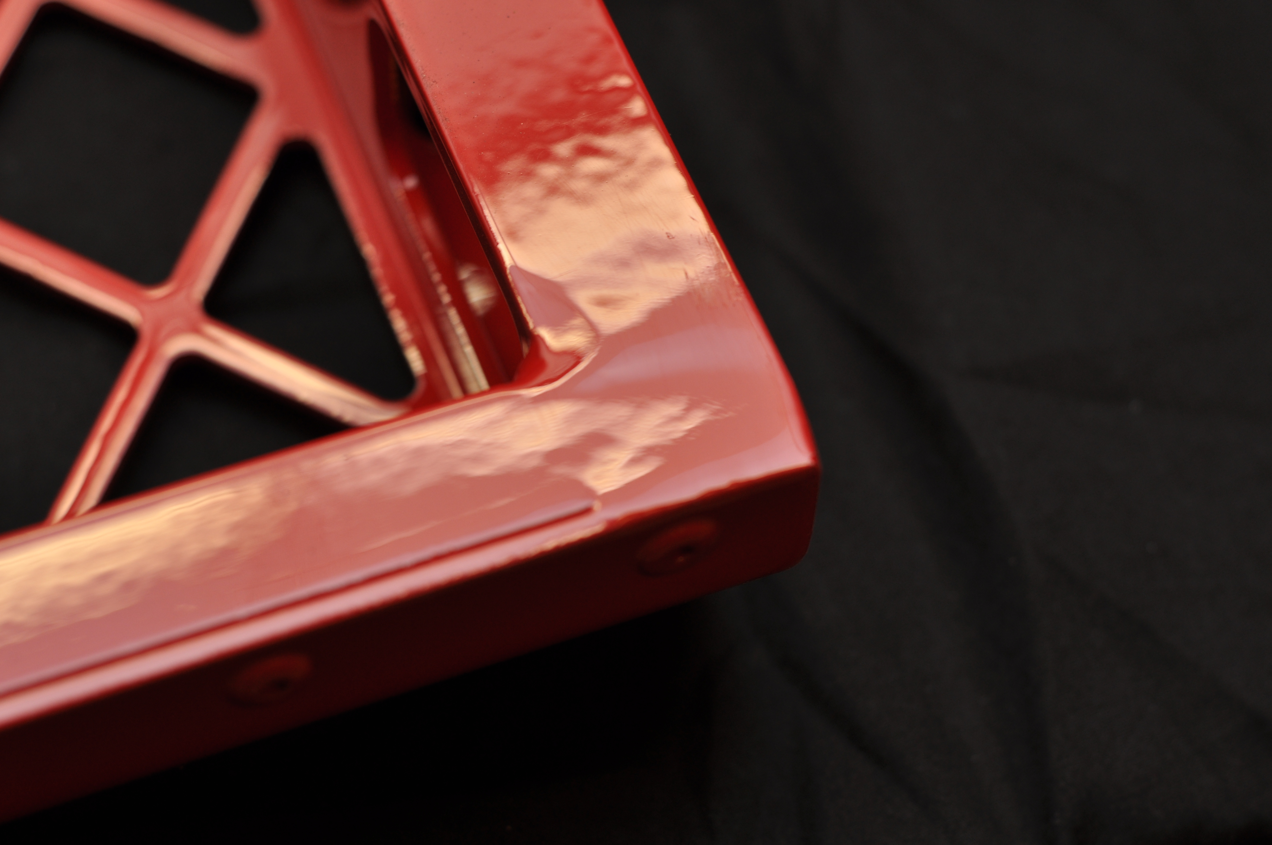
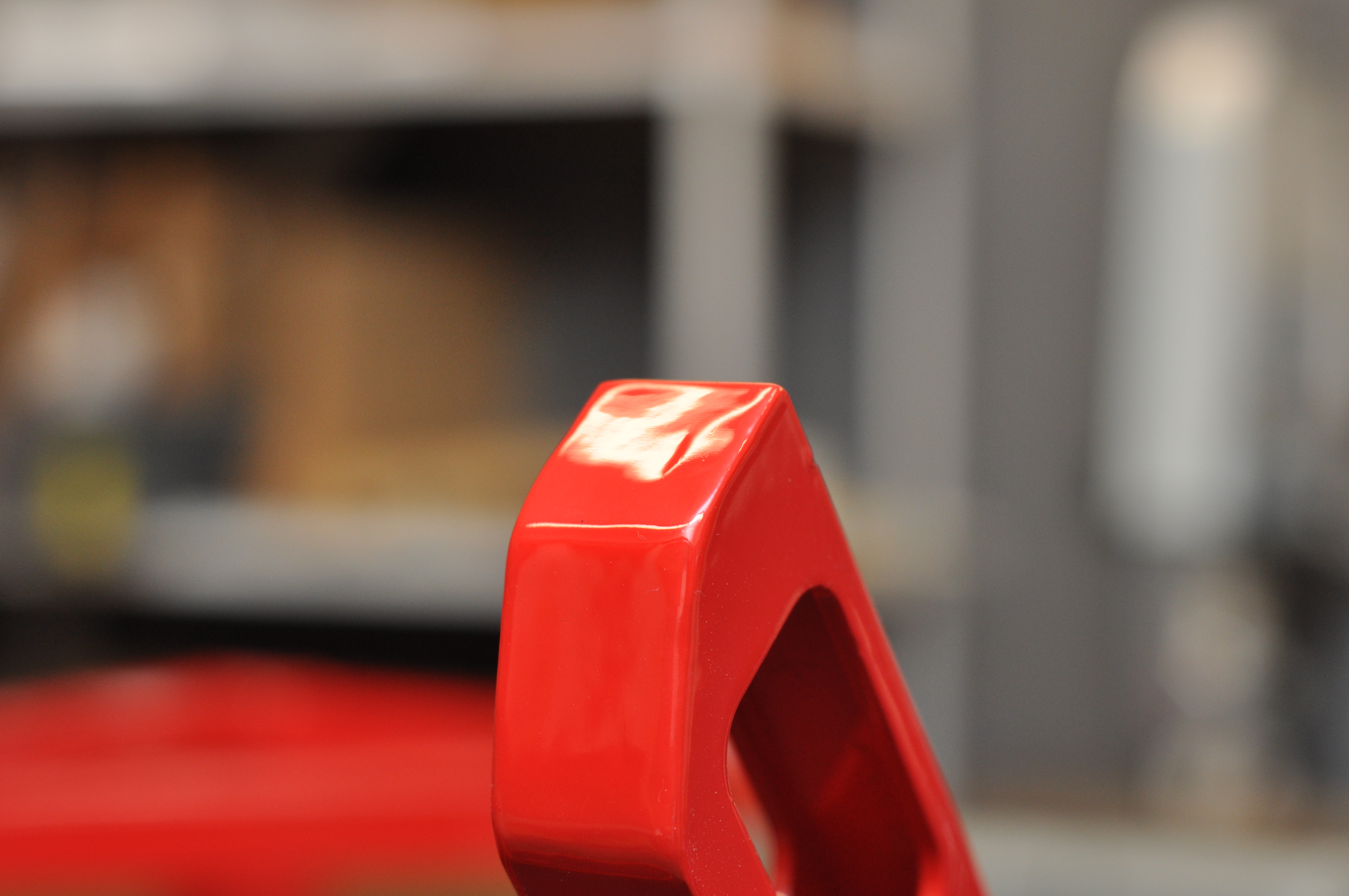
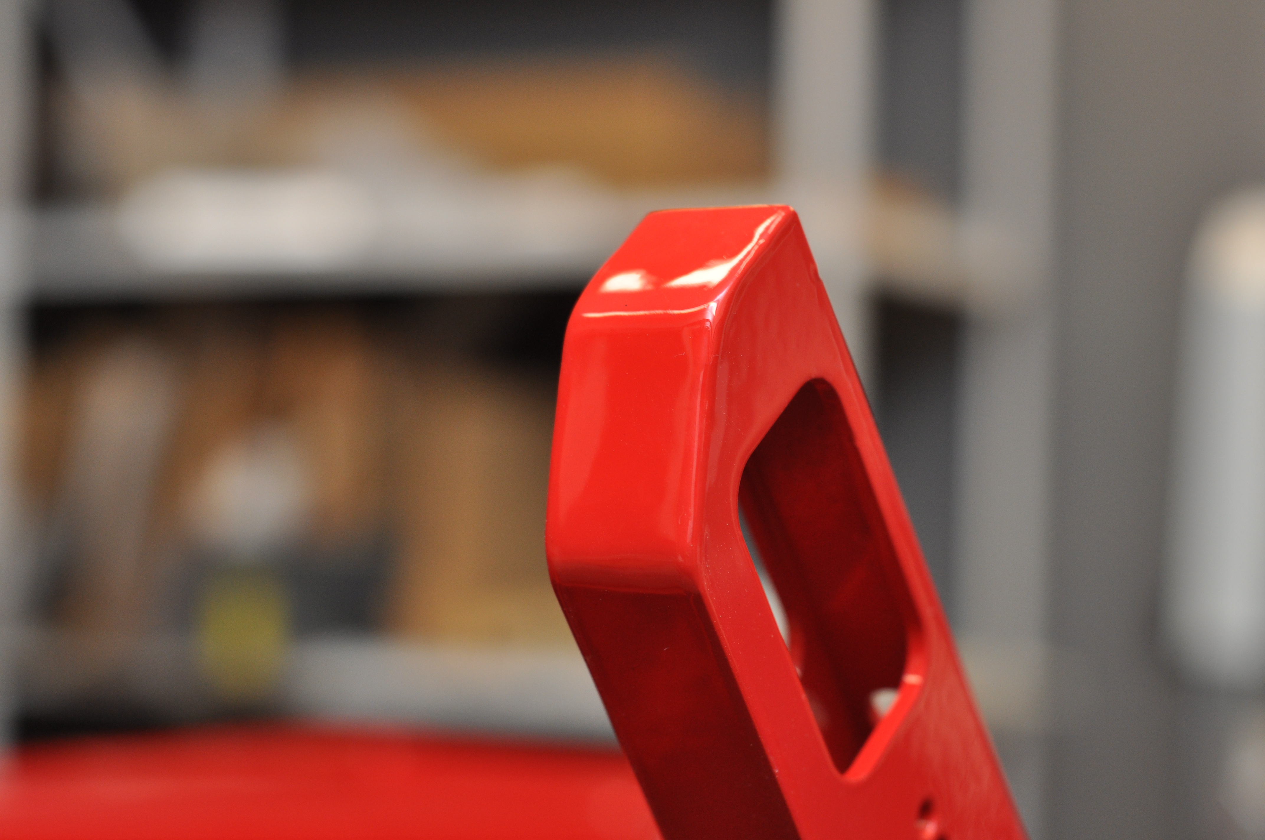
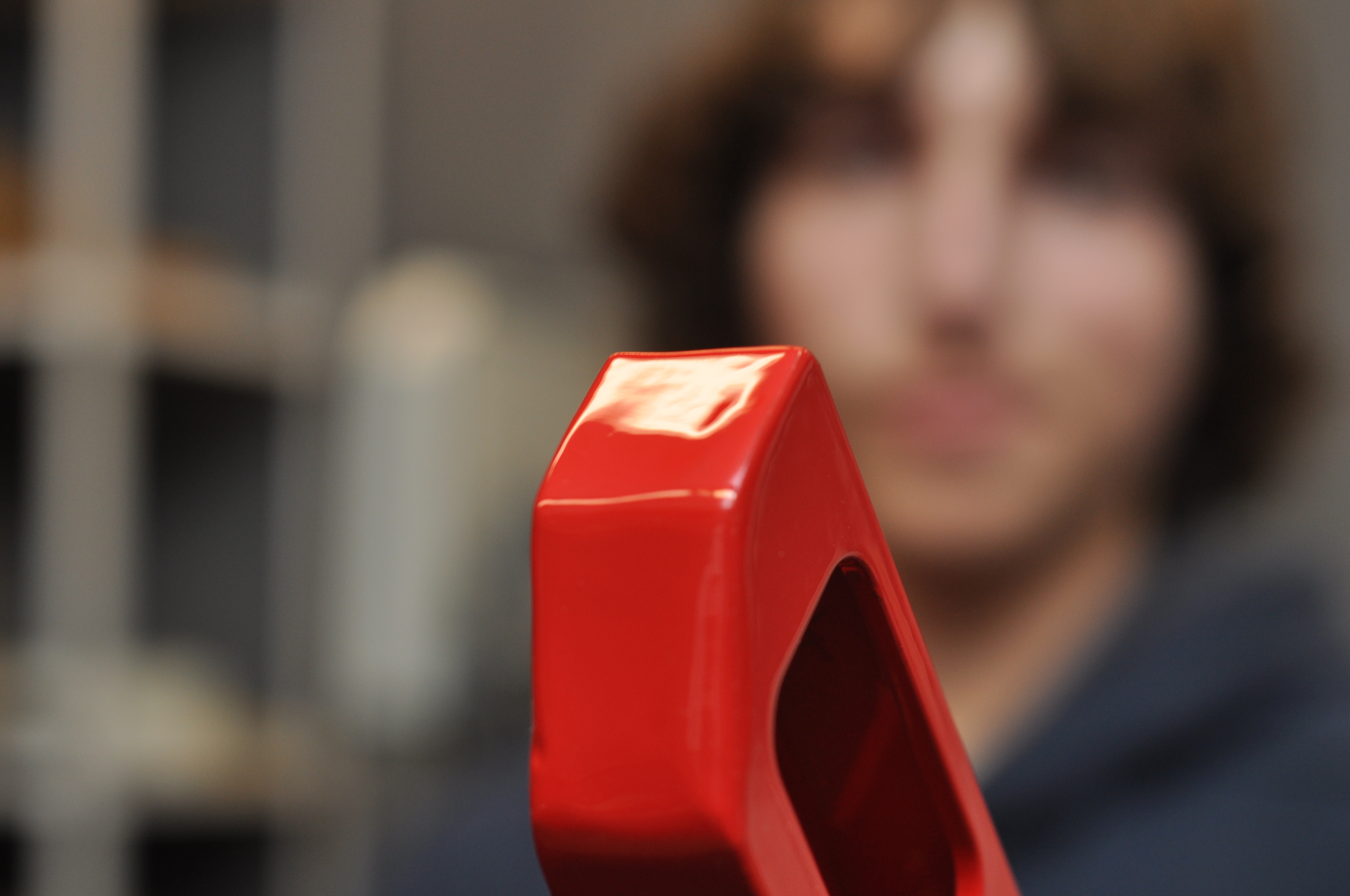
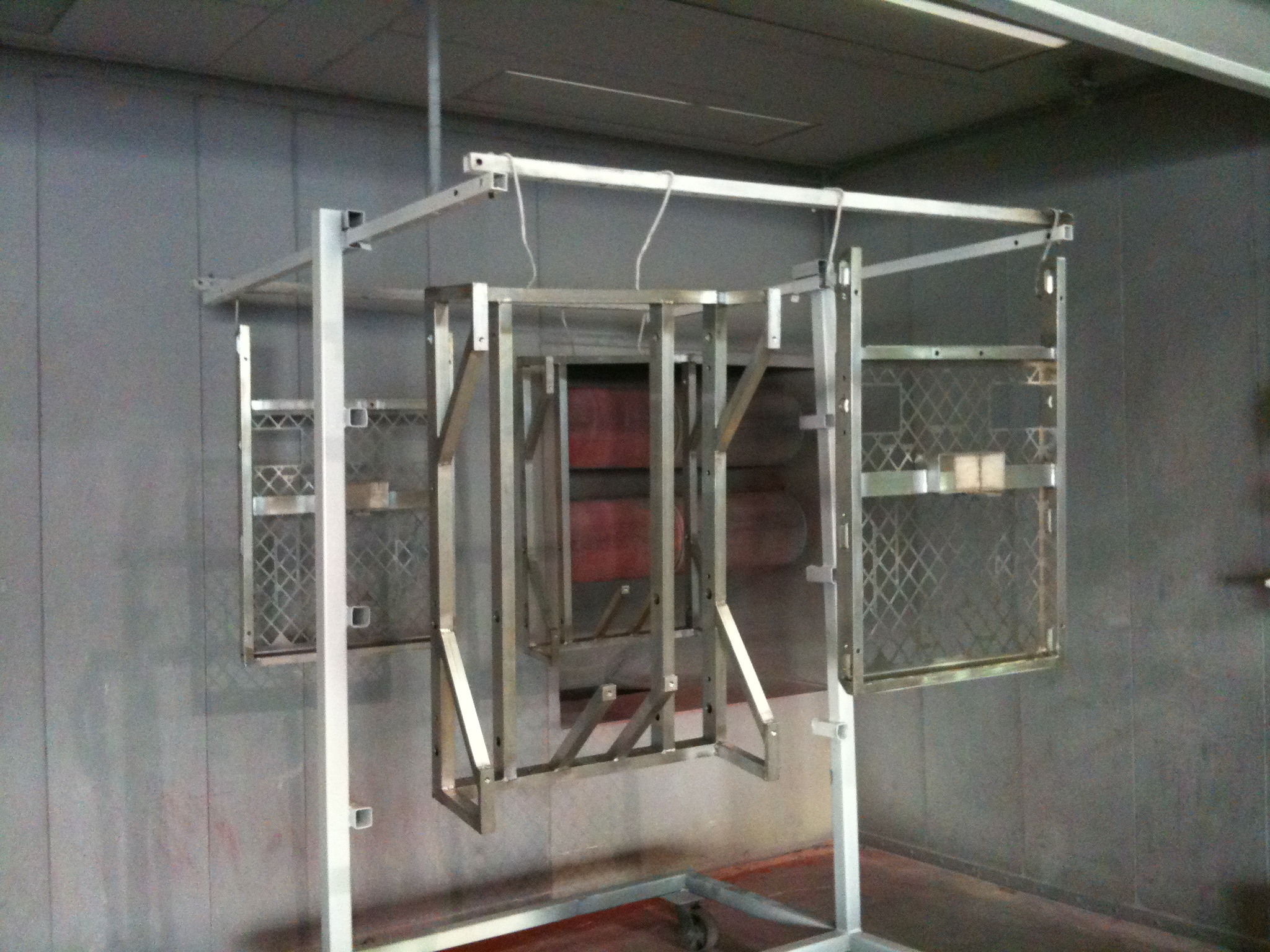
Unfortunately, Central Powder Coating was not well staffed today. They will have the 254 frames powdercoated blue streak #2 tomorrow morning.
Revised Control Board Layout
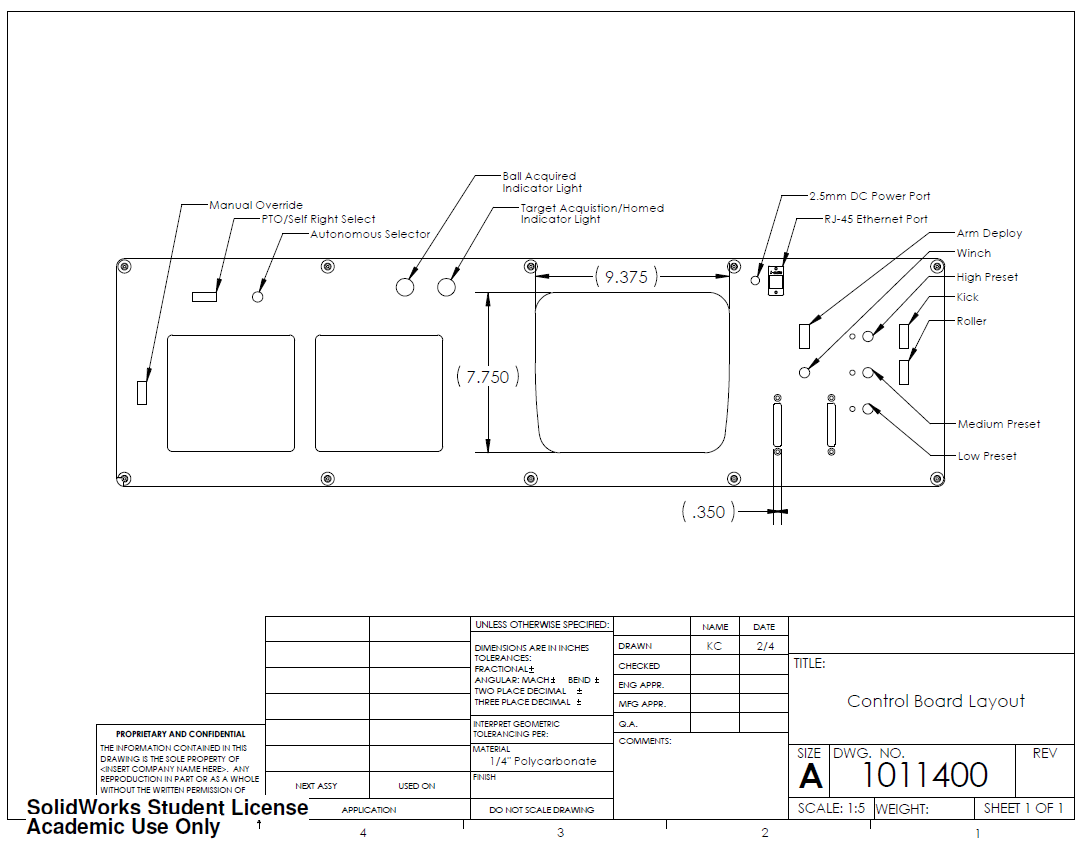
This revision includes the cutout for the Classmate pc, contours and filets for the ethernet jack, holes for the LED mounts, screwdriver slots for the Cypress board and finally, an additional cutout that replaced the roller button.
Progress
Manufacturing
Pacific Precision is able to make the output shafts; unfortunately they will not be done until late next week. We also confirmed that the robot frames will be ready to be picked up from Central Powder Coating at the end of business day Thursday. We continued progress on machining the bumper mounting pins, and will begin on the kicker piston bearing cones once the bumper mounting parts are complete.
Design
The control board CAD is being revised and we purchased all of the components for the boards.
Other News
We secured a local embroidering shop to make the team numbers on the bumpers.
We have contacted Motion Industries for a quote for all the ball bearings, and are currently awaiting word back.
Progress
MANUFACTURING
The manufacturing team has been working hard to complete parts for the drivebase. After completing gears and sprockets, we have moved onto the construction of the shifting dogs for both the drivetrain and the kicker winch.
DESIGN
The design team has been working to finalize a myriad of parts so that manufacture can begin. The plates for the kicker winch and arm have been finalized, and will begin being waterjet at BAE Systems tomorrow after the material is delivered. Design on the rollers is continuing, implementing the Clutch that we have purchased from McMaster-Carr.
Welding Complete, Off to Powder Coat
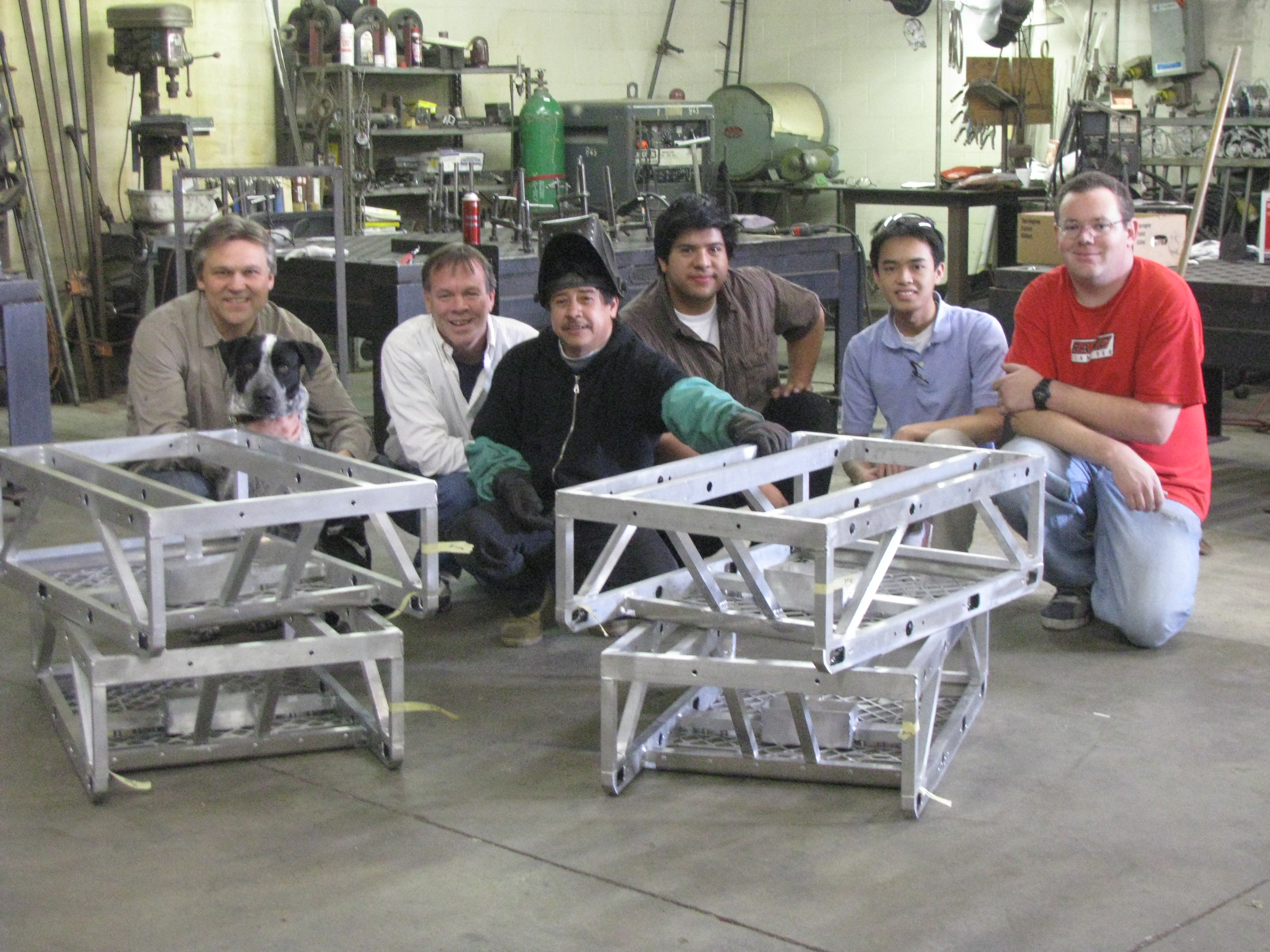
Today the welding was completed at Ride & Show Engineering, and the frames were delivered to Central Powder coating. The picture below shows us with the kind folks at Ride & Show.
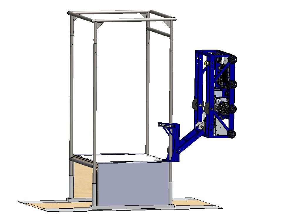
Control Board
Update: Here’s the newer revision of the control board. I’ve added an ethernet port and a female barrel plug for the Classmate PC.
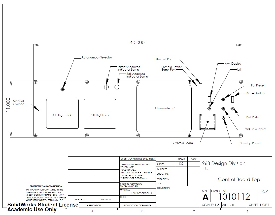
Here’s the first revision of the control board with a suggestion of buttons and functions.
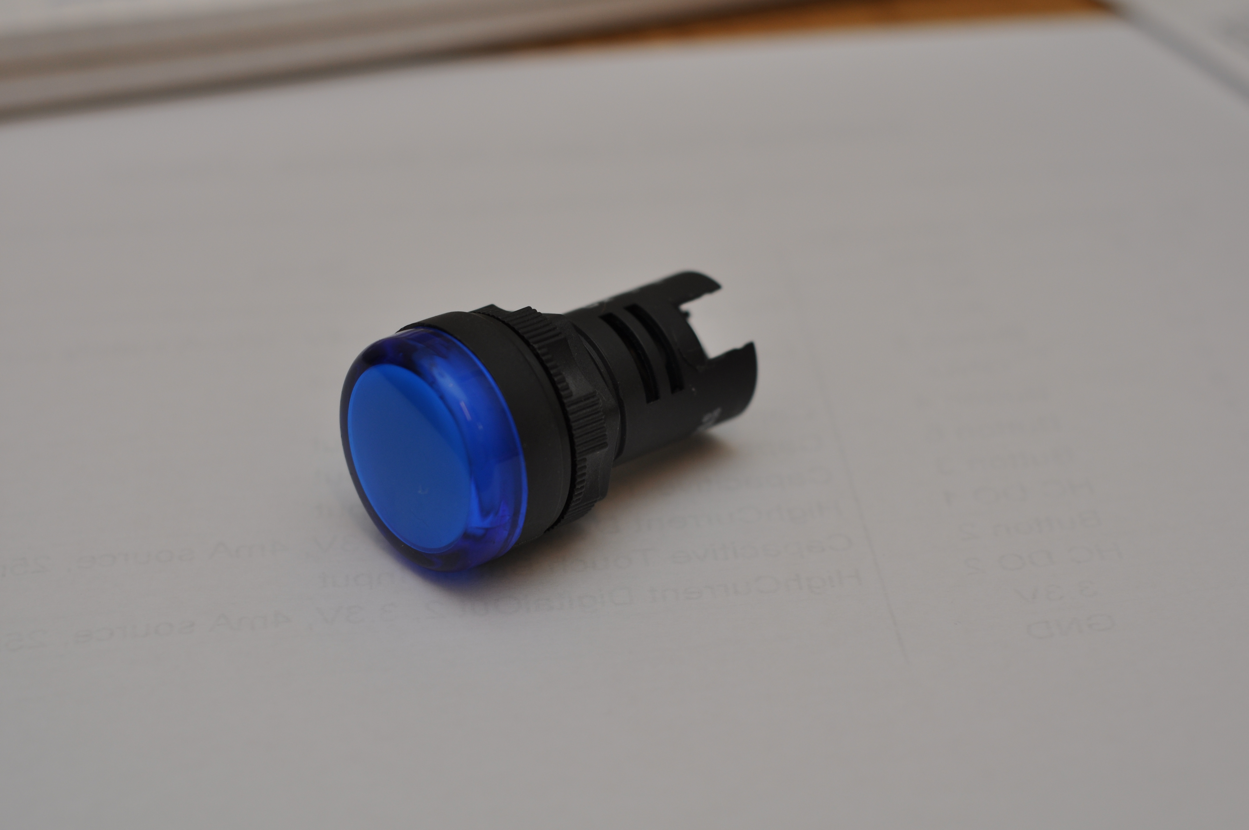
We will be using this LED w/Defuser(Red and blue??)
Roller Prototyping Progress
Today, we continued prototyping dual roller systems. We worked hard to emulate the drawings we had, but still found minimal success with the belt-driven systems. The faster the rollers were moving, the better the results. However, if the rollers were moving too fast, the window motors would stall and be damaged.
At the end of the evening, we strapped a Dewalt 3 Speed Drill onto the robot. With the shifter on middle or high speed and the clutch set very low, we were able to obtain and hold the ball extremely well. Videos of this system at work are below.
Original video unavailable.
Original video unavailable.
General Update
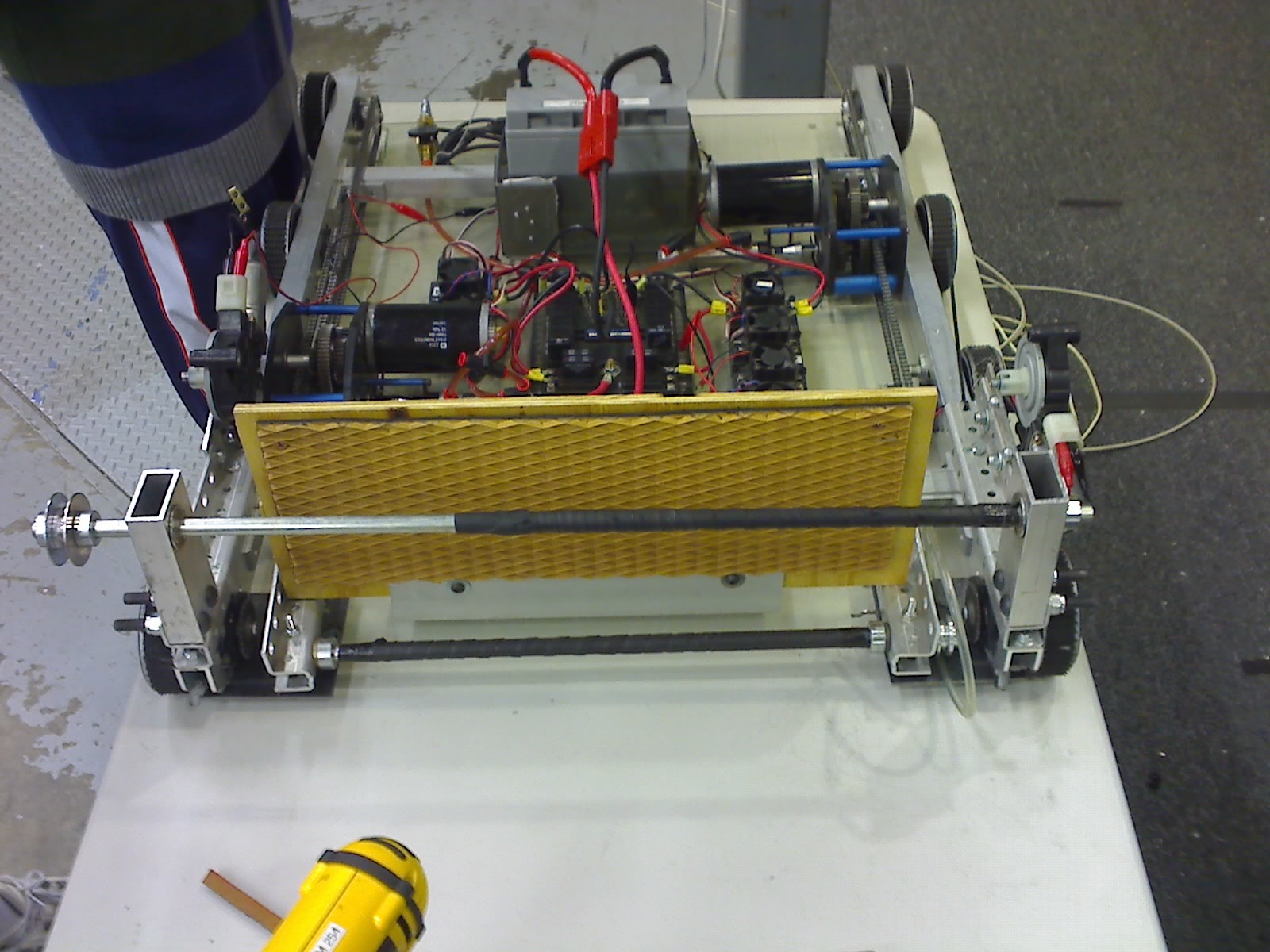
We continued to revise the two horizontal-rollers prototype so that it would be ready for proper implementation on the final design. Some of the most recent changes made include a stop, so that the ball is physically limited from entering more than 3 inches into our robot. Unfortunately in the earlier tests the ball actually entered 4 inches into our robot and roughly 1/16 inch off the ground. We also shifted the upper roller as forward as possible while retaining space for the bearing and moved the lower roller forward. The roller speed was also increased from the window motors with a 4 to 1 pulley reduction Videos should follow tommorrow after the design is perfected further.
Down in the shop we continued to pocket gears on the CNC and several sets for both the drive-train gearbox and the shooter winch gearbox have been manufactured already. Hopefully by the end of tommorrow we will be for the most part done pocketing the gears (at least the ones finalized on the design). They will be ready for ship by Monday or Tuesday.