41 posts

FRC Day 3 Build Blog

2017 FRC Build SeasonEmailParentsStudents#FRC#FRC Build Blog

Day 3: Progress in Prototypes

Prototyping

Double Wheel Vertical Flywheel

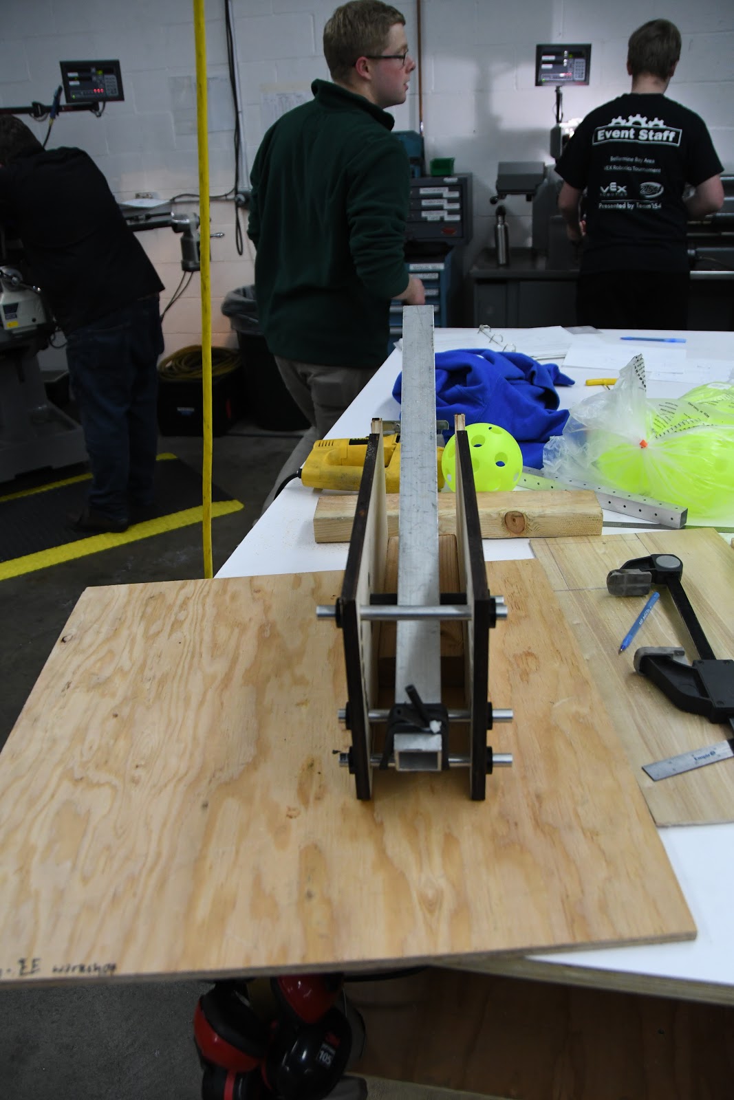
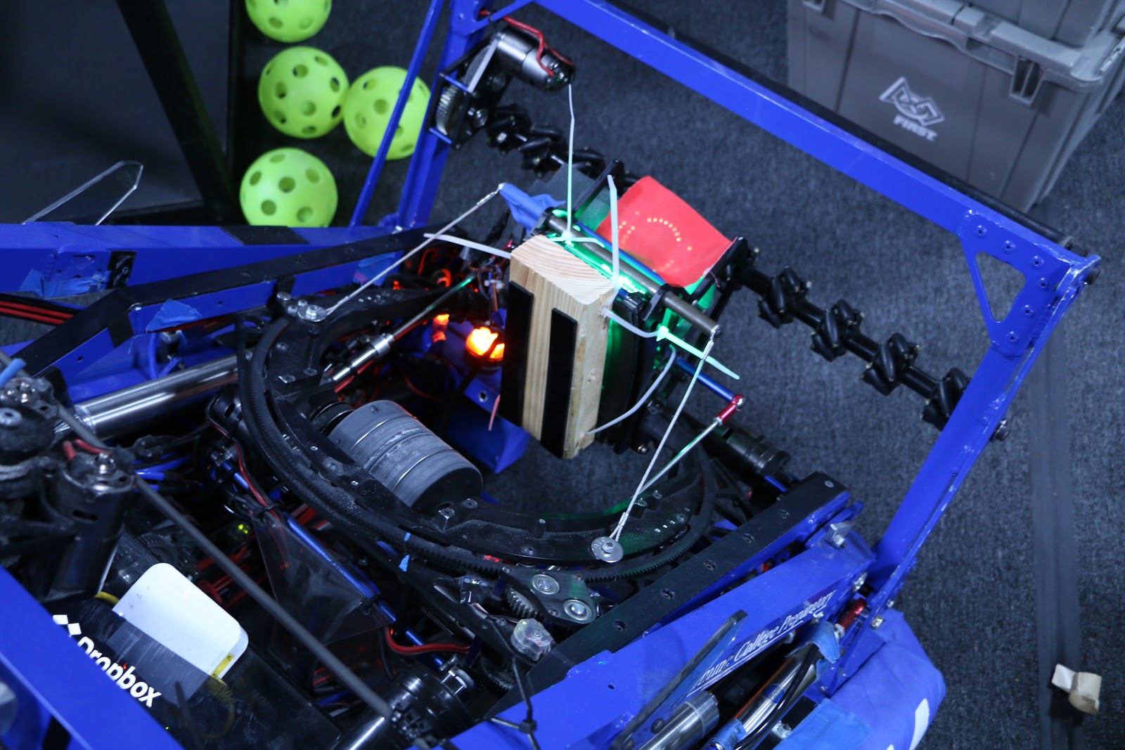
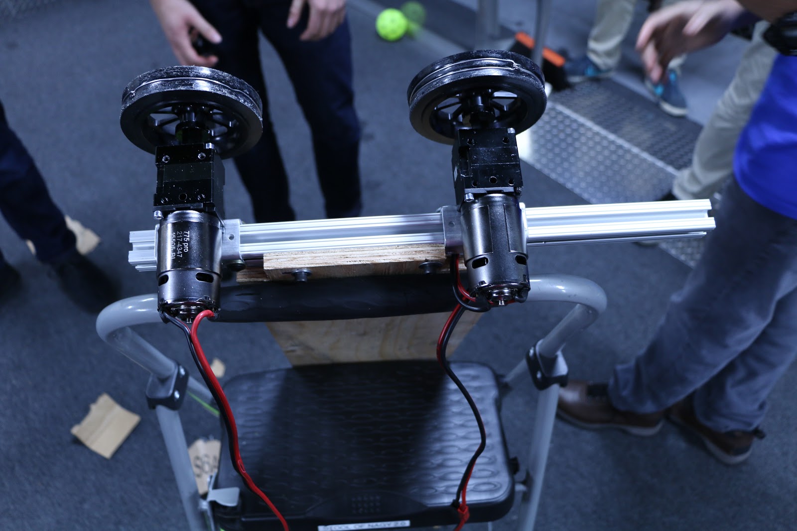
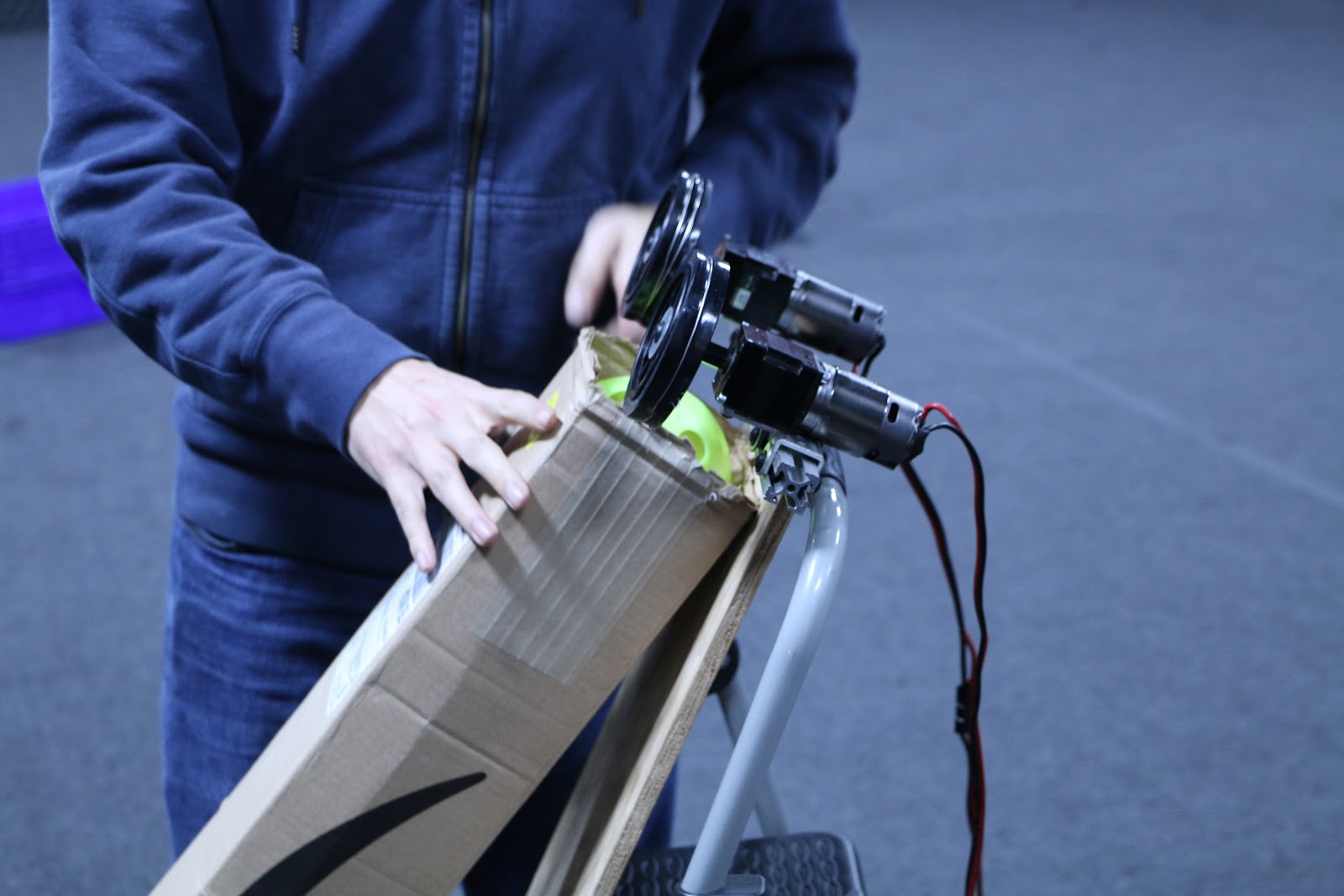
Today, we worked on assembling the Double Wheel Vertical Flywheel. Taking the parts from last build, we assembled it using the new VersaPlanetary gearboxes and encoders we received. We assembled the flywheel to our previous spec, but we had problems with the gears we had in stock. We changed the ratio in CAD and laser cut a new plate. After doing so, we assembled the flywheel. While the flywheel worked well after changing to polyurethane, the conveyor system failed. Rather than cutting a new plate, we cut a bearing hole and inserted a hex shaft on the inside of the polycord, essentially acting as a tensioner. This worked relatively well, but needs further refinement. We did prove our concept, and will further iterate to better understand how best to integrate our design with the robot.
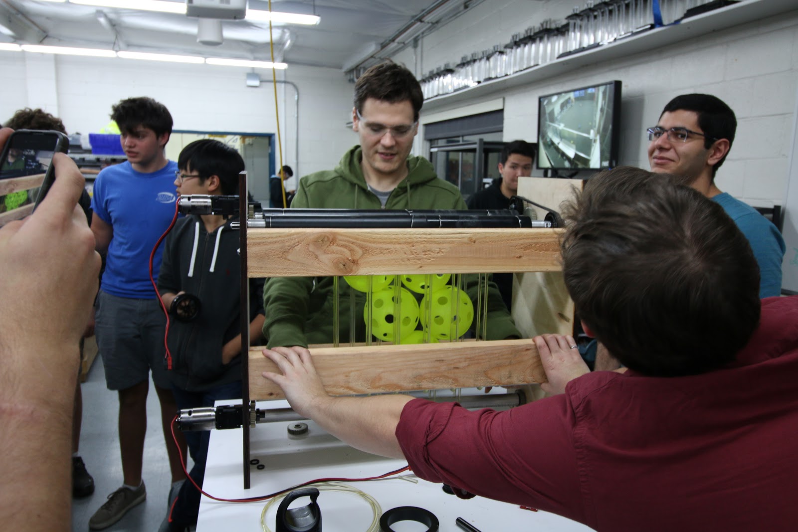
Testing:

For the Double Wheel Variable Compression Vertical Flywheel, we assembled the majority of the pieces and only need to insert the wheels to begin testing.
Fuel Intake

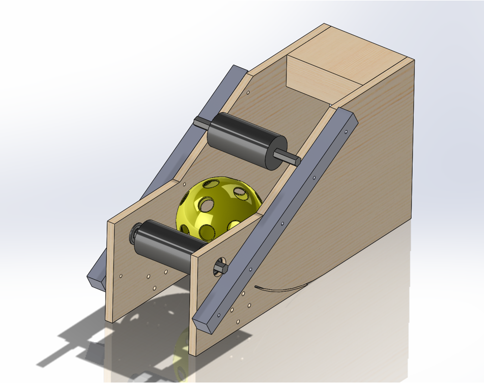
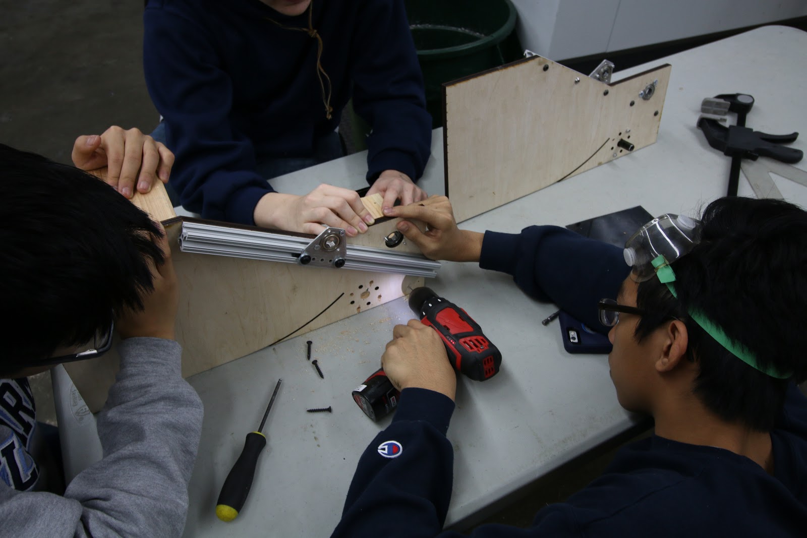
We finished assembly and began testing the belt intake, which was very fast when pulling balls in, but protruded several inches beyond the bumper. We began to design a new intake today, which will be much more compact and will therefore allow for a larger hopper and more room for other systems. This intake uses no belts, and two polyurethane rollers pull the balls up and over the bumper into the hopper. This removes the inefficiency and added complexity of belts, and makes the whole design cleaner and simpler. The intake's design is finished in CAD, but it has not been built or tested yet. On Friday we will laser cut it, finish assembly, and test it to see how effective it it..
Testing:

Gear Intake

The Gear Intake development process continued today with the construction of a recently CADed design that has an inner slider in order to pinch the gear between the claws and itself. This process was difficult because the .25” plyowood that was used for construction is actually .2”, so the original design needed to be modified slightly so that all the pieces would fit together. Other small improvements involved adding polyurethane strips to the inner slider and the claw so that the whole system grips onto the gear well.
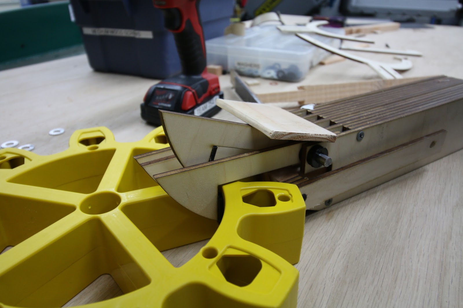
Testing:

Drivebase

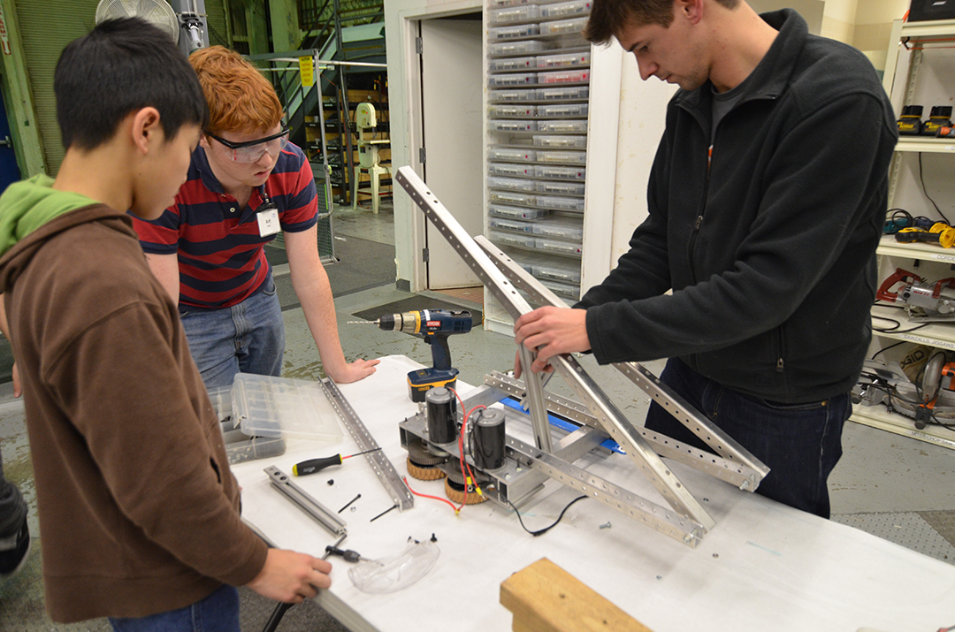
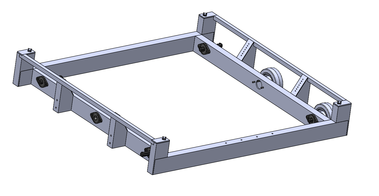
We finished an initial weldment of the general structure modeled after our 2014 robot and the side rails/bearings/housings modeled after our 2016 robot. Taking bumpers and an intake into account, the frame was dimensioned to fit within the 36" by 40" by 24” size limit.
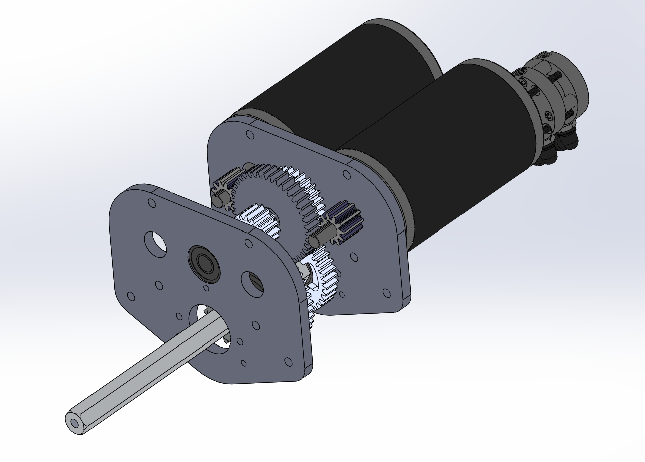
In addition, we designed the drive train gearbox in CAD with 2 CIM motors per side in a 2 stage reduction with a dog shifter and pancake piston to have 2 speeds: low gear for pushing force and high gear for maneuverability. With the design almost done, we only have to add spacers, intermediate shaft, standoffs, screws and nuts, retaining screws, and pocketing to the CAD (members can access the design from pdm under the name 254-17-A-0300 Gearbox if you want to see or help design it).
Climber

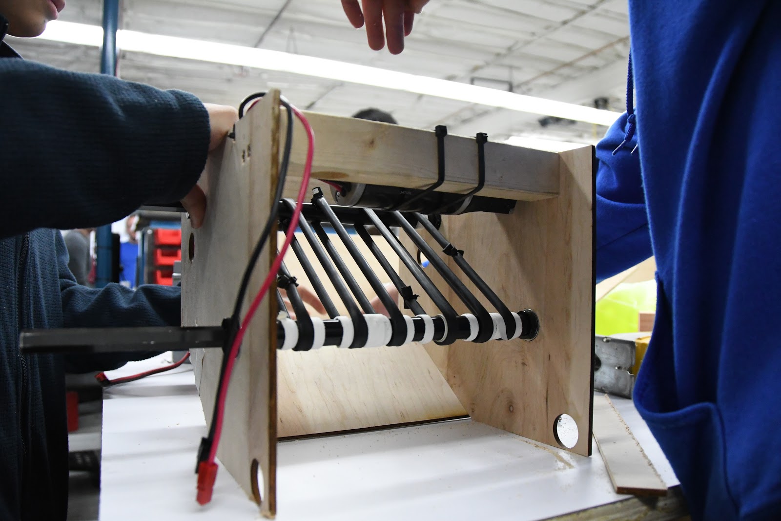
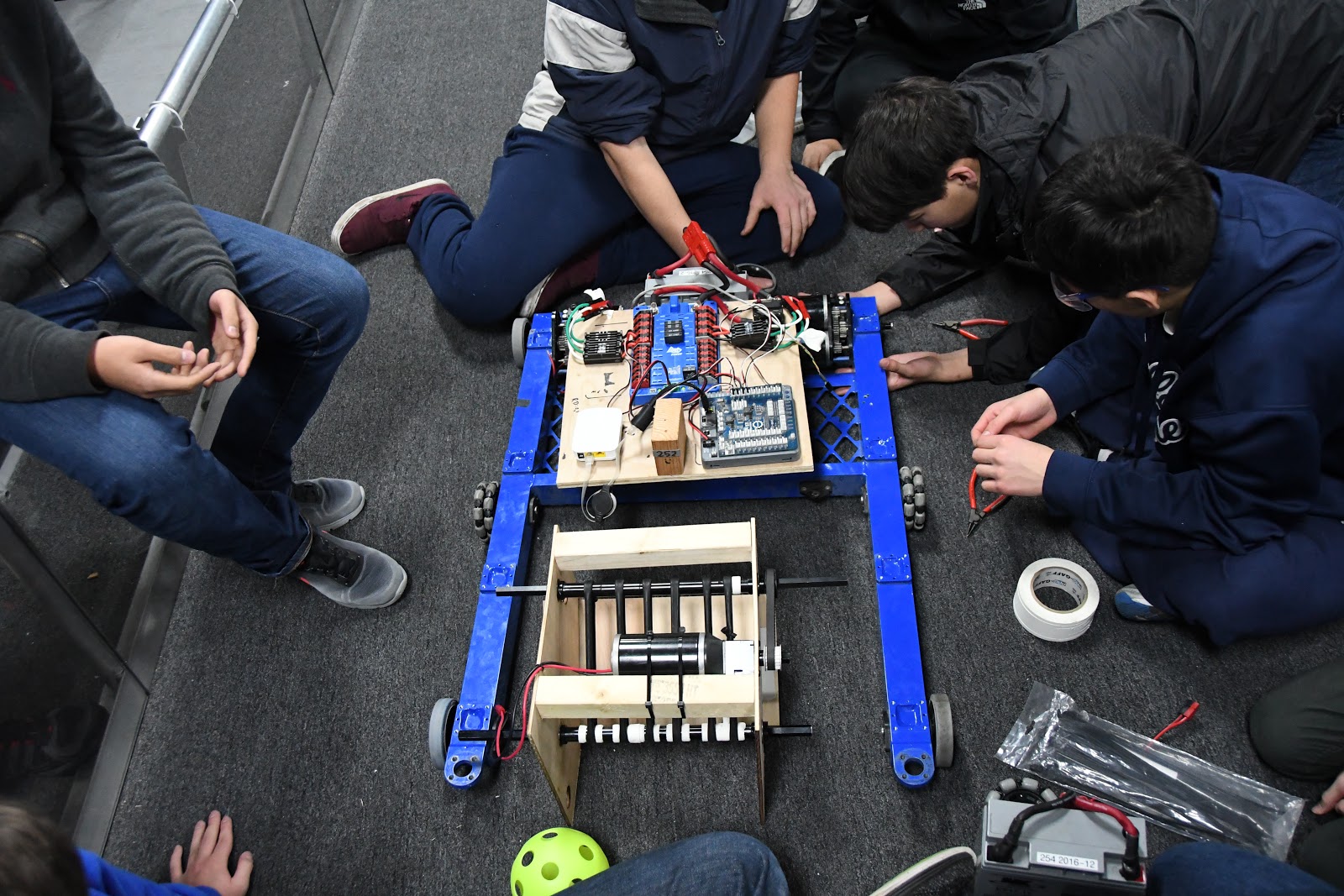
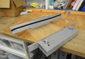
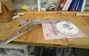
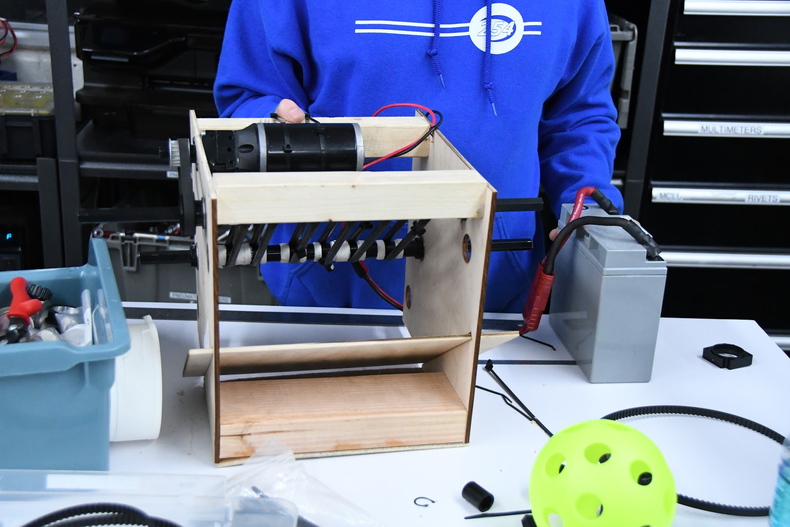
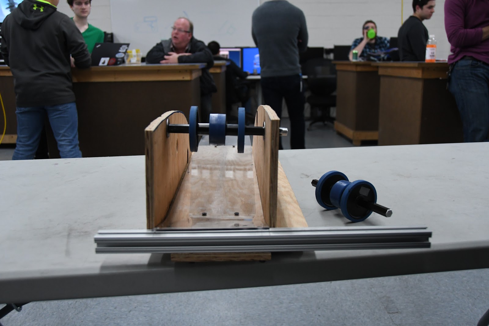
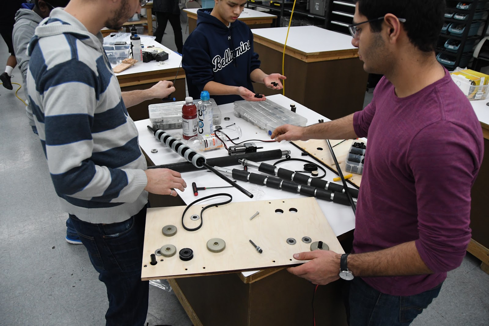
Today, we designed and began to build prototype mechanisms for climbing the rope. The prototypes for actually holding onto the rope included variations combs with differing spacing. We began working on a standard mount for each type of prototype climbing roller. We decided to use a VersaPlanetary gearbox in our build, using a gear ratio of 1:90 to heavily reduce the rpm of the motors from ~18,000 RPM and increase torque to ensure the robot could lift itself. We then assembled the multi-stage gearbox, attached the motor, and soldered the battery leads. Lastly, we began the process of building a frame and prepared the parts to completely assemble the mounts next build.

Programming

Control Board

On Wednesday, we met up and worked on control systems for recent prototypes and we also continued developing pixycam communication. We added three talons to the prototype board to support the growing complexity of prototypes.

Robot Programming

With a prototype board ready, we added feed-forward PID control to our two-roller shooter prototype. PID is a control loop that keeps a constant motor speed, allowing us to effectively test the shooter prototype.

We also rewrote a majority of our code using elements from last year’s code, to avoid re-inventing the wheel. The new code is far more scalable and efficient. In particular, we implemented Loopers, a structure that runs code extremely fast, and compartmentalized our code into the various (potential) subsystems on the robot. We also discussed code conventions to ensure uniformity in the code down the road.

However, we had issues with compiling and deploying the code due to issues with the motor controller driver. We’re resolving those issues down the road.

Camera Connectivity

We worked on camera connectivity, finishing a testable version of an SPI driver built on WPILib for the RoboRIO. Previously, we built a native library that allowed us to communicate with the PixyCam over USB and wrote a JNI wrapper to let us invoke the native code from Java, but today we encountered issues when connecting to a physical PixyCam. Rather than debugging the USB connection, we decided to ensure that we could build a reliable SPI driver first, as we are confident that we will be able to communicate with the camera over SPI. Though a USB interface would be optimal, it is significantly complex and we plan to work on that functionality once the SPI driver is confirmed to work as expected.. We added a new pinout to the PixyCam and connected it to an old RoboRIO board for testing. To help with testing, we connected the PixyCam to a computer and trained it to recognize the yellow game balls. In the upcoming builds, we will proceed with testing our SPI driver with an old RoboRIO so we have a working method of connection for this year’s code.
FRC Day 2 Build Blog

2017 FRC Build SeasonEmailParentsStudents#FRC#FRC Build Blog

Day 2: Prototyping

Today, we continued our work on prototyping designs for the shooter, intake, and drivebase. Our programming team also worked through a variety of projects including camera calibration and configuring the RoboRIOS.

Shooters

Double Wheel Horizontal Flywheel

We assembled the feeder for the horizontal flywheel shooter using three wheels of two different sizes to optimize contact with fuel balls. We determined that we would either use polycord or rollers for the feeder. However, due to availability of resources, however, we decided to prototype with a wheel roller. The horizontal flywheel was ready for testing but is still waiting on more planetary gearboxes.

Double Wheel Vertical Flywheel

Today we continued working on developing a double wheel vertical flywheel. In the process, we tried to optimize throughput with the limited space available on the robot. Initially starting with a hand loaded prototype, we combined the shooter with a conveyor prototype to remove the variables of human error.. We managed to design and laser cut the sidepanels for the prototype, and began assembly. We have organized the VEX Pro VersaPlanetary gearboxes and will implement it on Wednesday.

Another project based off a double wheel vertical flywheel aimed to optimize the best materials and fuel compression to maximize accuracy and shot speed. We spent the build designing a model in Solidworks to later be laser cut.. By the end of build, we acquired all the materials for the prototype including the 80/20 Extrusion Material, T-nuts, modified Versa Side Bearing Motor Gussets, 2 x 4 Wood Blocks, Bearings, and laser cut to design ½” Plywood.

Catapult

We improved the catapult and eventually hit an accuracy rate of 15/15 into the high goal. The improvements we made include:

  • Adding a stronger shaft

  • Tightening the medical tubing that provided the power to pull the shaft to the hard stop

  • Moving the hard stop and axle into the optimal position

  • Figuring out how to calibrate the machine

  • Securing the catapult to a piece of plywood so it wouldn’t move after every shot.

The design still needs a lot of improvements based on the power applied and the contact with the ball to make it into the boiler quickly and consistently.

Testing:

Intake

Today we took the intake prototype from yesterday and added several more surgical tubing belts in order to pull in more balls at once. In addition, we resized it for better geometry and added a CIM motor for lots of power. The results are very successful, and we are able to rapidly suck in several balls at once over a bumper, meeting our original goal for this prototype. The next step is to mount it on our practice drivebase and see how well it can intake once in a robot. We prototyped this specific intake because we have used similar ones in the past successfully, but were unsure how they would react to the plastic balls compared to more traditional foam balls.

Testing:

Drivebase

Today for the 2015 Deadlift drivebase we installed a new radio with updated 2017 firmware in order to successfully connect to the driver station. Additionally we experimented with different types of wheels. Initially we started with colson wheels on the outside and an omni-wheel for turning. The idea was that due to the center drop of the drivebase we would only be on an omni, and a colson wheel at all times. In order to optimize for turning we changed to all omni wheels, yet the turning was erratic so we think another set of wheels would be best for this game.

Gear Intake

Today we worked on the gear intake for the 2017 FRC Robot. The process involved spending a little bit of time on CAD to create a preliminary design, and then following up by actually laser cutting the wood pieces and then putting them all together. After that, we experimented with different heights for the grabber pieces on the claw to figure out which angle would be optimal in sliding up and over the edge of the gear. The next step in this project will be to cad a significantly more robust version of a similar design, as well as add a system for actually “grabbing on” to the gear so that we can manipulate it.

Testing:

Programming

A lot got done in programming today! We had our first build meeting and we will be having subsequent meetings every build where we will get anyone involved who wants to work on something. During this build we divided the work into the following tasks:

  1. Installing updates onto drivers stations

  2. Camera USB to RoboRIO Communication

  3. Camera Calibration

  4. Programming prototype boards

Driver Stations

We successfully updated the driver station software on the driver station computers. Now, everything works well.

Camera USB to RoboRIO Communication

Since last build, we successfully cross-compiled libpixyusb to the RoboRIO’s ARM architecture using QEMU on Ubuntu. We then created a JNI for it so that we can integrate it into our codebase. However, it has not been tested yet and we will be doing this throughout the week. If his port works, then we will not be using SPI with the Pixy Camera

Camera Calibration

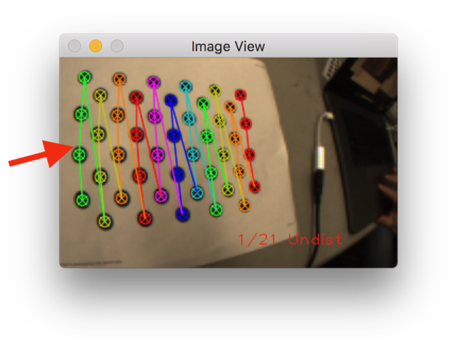
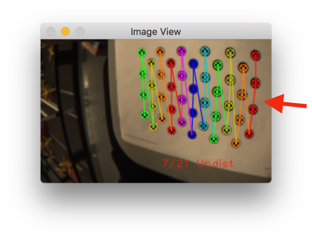
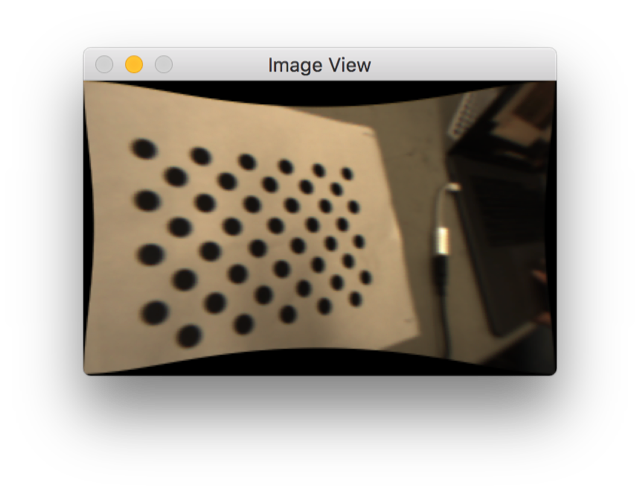
The goal of calibration is to get rid of the distortion in the camera. Here are some screenshots that illustrate this distortion:

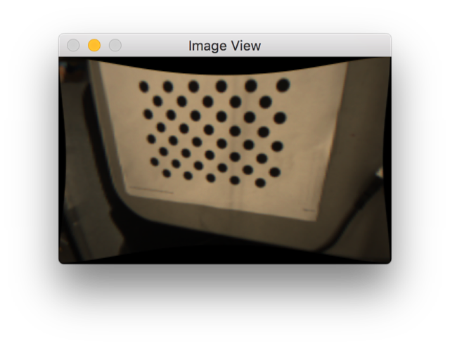
After the calibration, the dots in the image or more linear and the edges of the dot grids are parallel. This is the result of the calibration:

With better calibration, we will be able to more accurately approximate the angles of the goals so that we can make the targets. The calibration above isn’t perfect, but we are still working on making it better. The current issues that we have encountered are mostly due to the low resolution of the pixy camera which prevents OpenCV from recognizing the dots at more oblique capture angles. If it were higher resolution, it would generate a more accurate calibration.

Robot Programming

This build, we successfully configured the RoboRIOs and programming computers to use the latest version of FRC software, albeit with a few hiccups. In techno-speak, the RoboRIO wasn't assigning itself a static IP address, leading to communications problems. The programming subteam was able to overcome this issue, albeit with a temporary fix.

FRC Day 1 Build Blog

2017 FRC Build SeasonEmailParentsStudents#FRC#FRC Build Blog

Day 1: Kickoff & Testing

Today was the first day of the FRC build season. The new game, FIRST Steamworks, was revealed, and we began evaluating strategies and testing prototype mechanisms for our 2017 robot.

Helpful Links

The game manual and rules are linked below. All team members should familiarize themselves with the manual, especially the Match, Game and Robot sections.

Game animation:

Game manual.

Prioritization & Strategy

To evaluate potential strategies for our team, we estimated times to perform tasks such as picking up and depositing gears, collecting balls, hitting hoppers, etc. We then compared that time to the point value of each task to determine a priority list of items to prototype as well as to begin match strategy.

For 2 strong robots working together in eliminations, an optimal strategy could be to each perform a 2 gear autonomous and then in teleop do 2 “hybrid cycles” in which they each score both a round of 100 balls and a gear followed by 2 “ball cycles” where they score only balls. This would produce a maximum score (assuming 80% shot accuracy) of 410 points. Perhaps the third robot could play defense rather than contributing offensive points.

More information on this strategic analysis can be found in this spreadsheet.

Prototyping

Today, we started by prototyping various mechanisms to accomplish each of the tasks in the game. Later, we will work to evaluate the prototypes, determine which are most promising, and integrate them together for more comprehensive testing.

Shooters

High Throughput Shooter -

We discussed creating a shooter which can shoot a large number of balls very quickly (goal is 50 in 1 second). This will need to be designed, built, and tested in the coming week.

Single Wheel Vertical Flywheel - back spin -

We made a prototype for the vertical flywheel by modifying the hood of dropshot. We found that the shots often were inconsistent depending on the orientation of the wiffle ball holes.

Testing:

IMG_0439.JPG

Single Wheel Vertical Flywheel - front spin - We reversed dropshot and tilted it backwards to use the same flywheel but give the balls front spin instead of backspin. The balls still veered and had the same problem as backspin

Testing:

Double Wheel Horizontal Flywheel - This looks like the most promising prototype we have so far. It reduces spin on the ball to minimize the wiffle effect on trajectory. We are going to change this to a vertical double flywheel so that we can lengthen the wheel and shoot multiple balls side by side.

Testing:

Double Flywheel Prototype.jpg

Double Flywheel Prototype 2.jpg

Ball Intake - The preliminary plan is to have the bumper not at the limit of the maximum size so that we have room to deploy an intake in front of the robot (past the bumper, but within the maximum size). Although we could have a bumper gap, the maximum gap is about 14” and this setup would allow us to intake the full width of the robot which could be much faster and easier. It has been modeled in CAD and laser cut, but we have yet to assemble the prototype.

Catapult - A prototype was started for a spring-powered catapult shooter. This prototype needs some additional work to determine feasibility.

Gear Manipulation Mechanisms

Hook - We prototyped a one-way latch that is latches into one of the holes in the gear and then is pulled back into the robot to hold the gear with friction. This could then be actuated to tilt up and down to move from a floor-loading position to a hanging position. We made a new version with two hooks to allow for more misalignment when picking up the gears on the field.

Claw - A second prototype was built with two motorized wheels which intake the gear off the ground. The wheels are mounted to sprung arms which open around the gear as it moves in. It seems to work, but the quick prototype has the wheels spinning too quickly. We are going to work on slowing it down.

Drivebase - We have tentatively ruled out any sort of strafing drivebase because we don’t think it will be necessary. We will most likely use a 6-wheel or 4-wheel drive robot, as the team has high familiarity with these designs and should be able to construct them effectively and quickly. We are currently working on evaluating the best wheel configuration to have the ideal maneuverability by adapting Deadlift’s (2015 robot) drivebase with different wheels. We ran into some minor issues with radio connectivity, but we plan to fix this by using a newer radio. We need to finish the prototype.

Rope Climbing

Comb prototype - We discussed using a custom rope for hanging, likely a narrow, strong rope (like paracord) with knots. This prototype uses a comb-like hook to grab the knots and reel in the rope to pull up the robot and hang. We have tested it passively, but have yet to determine if it can support a robot’s weight.. There is still lots of work to be done, especially in optimizing the shape of the comb / spool so that the radius does not change too much as it rotates (necessary for gearing optimization).

Testing:

Programming

We started programming this season by creating a private code repository on Github based off what we did last year. We then started working on our demo boards, imaging them with the new 2017 firmware and installing driver station software to them. We also began experimenting with a Pixy camera for vision tracking. It seemed promising and easy to configure, but it didn't communicate easily with the roboRIO so more work is needed.

Day 43: Scrimmage Part 1

2014 FRC Build Season#FRC#FRC Build Blog

The Scrimmage

By Ryan Johnson, Louis Lin, and Alex Cherry

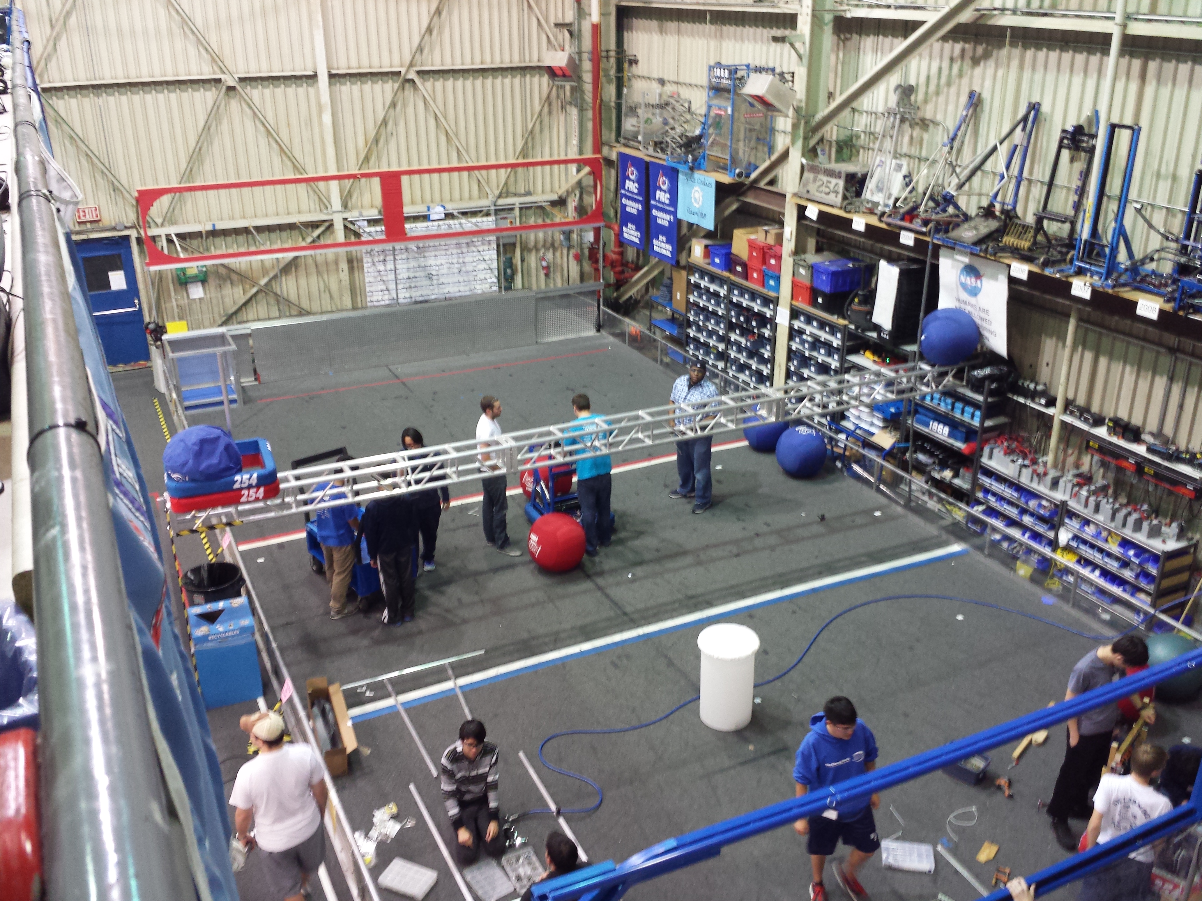
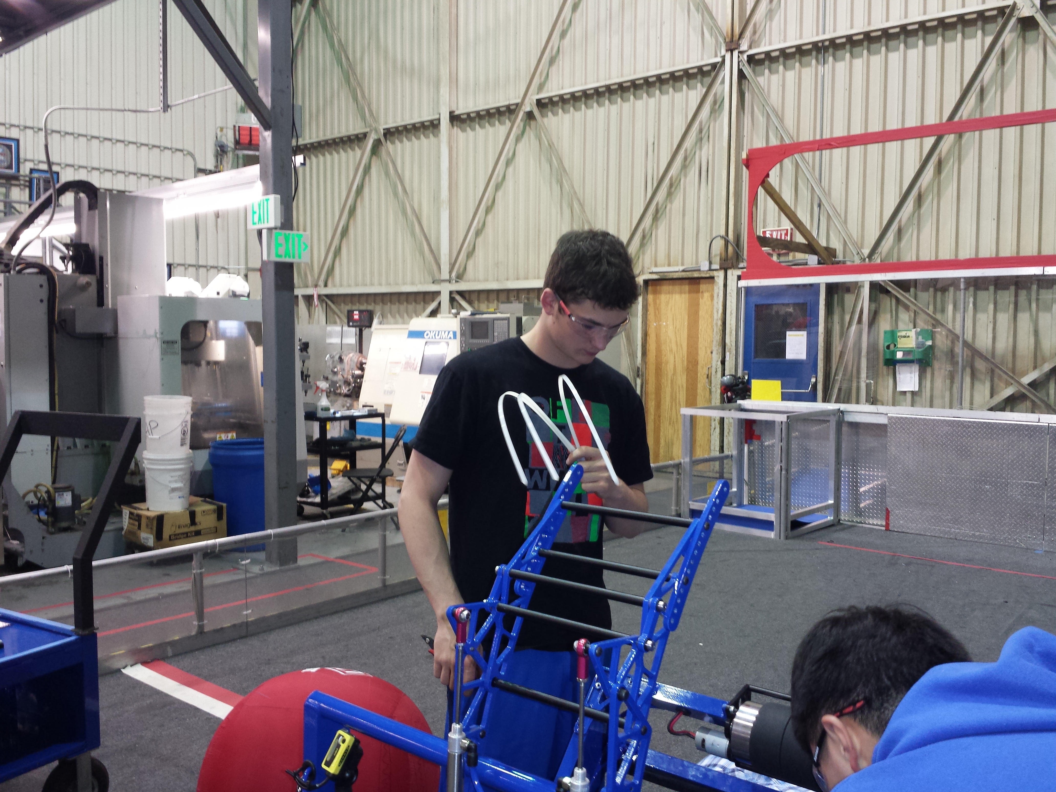
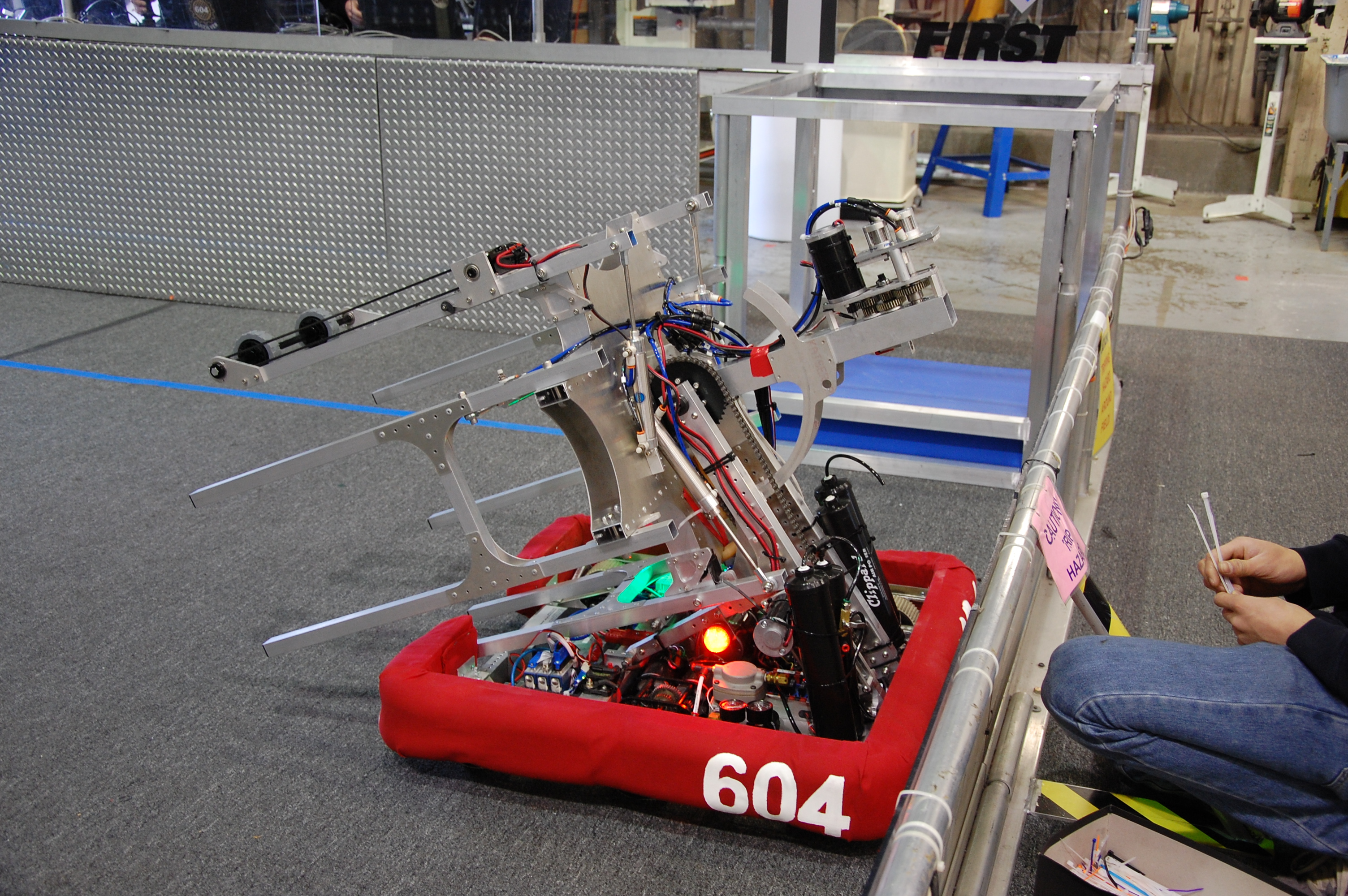
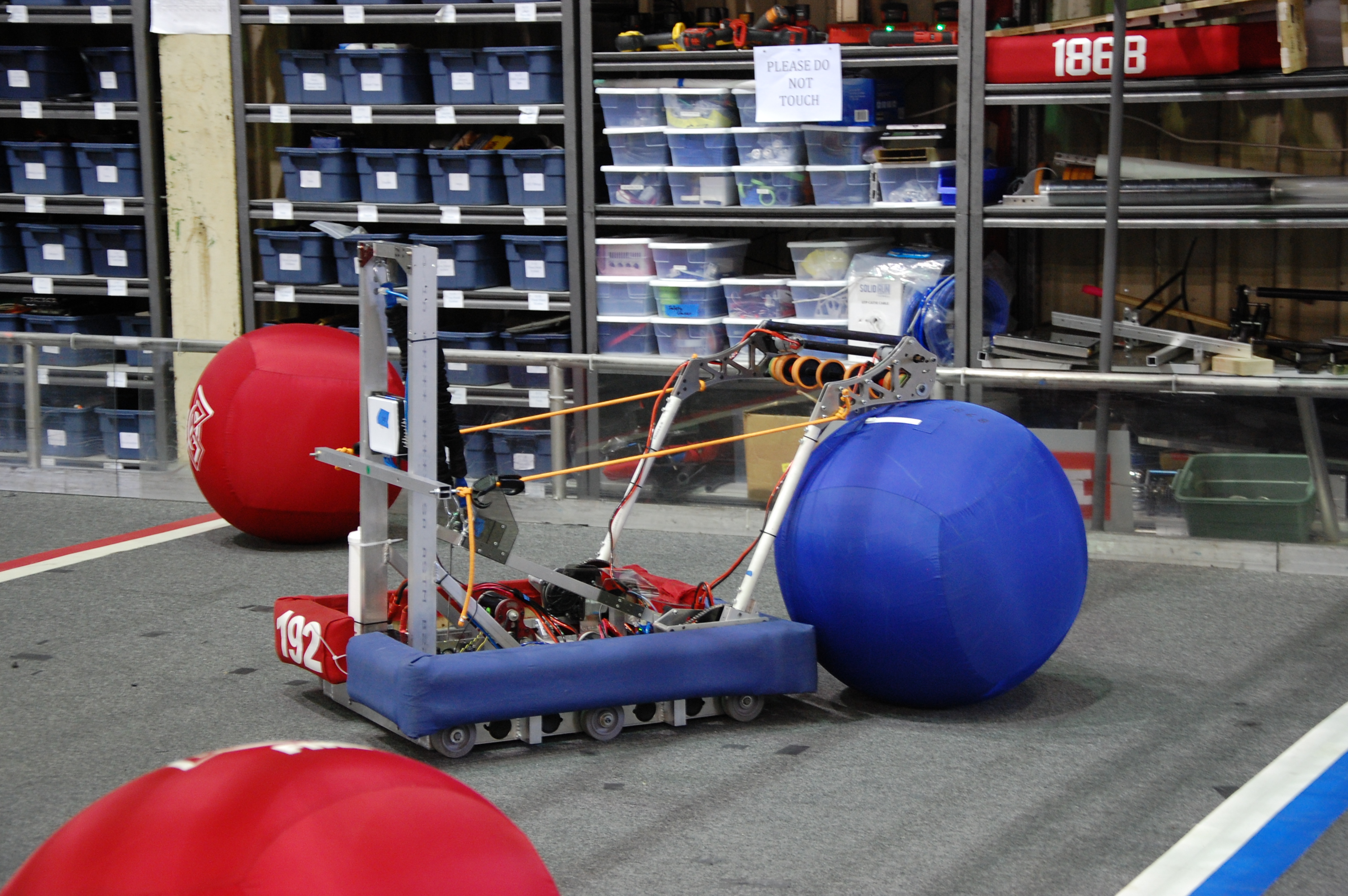
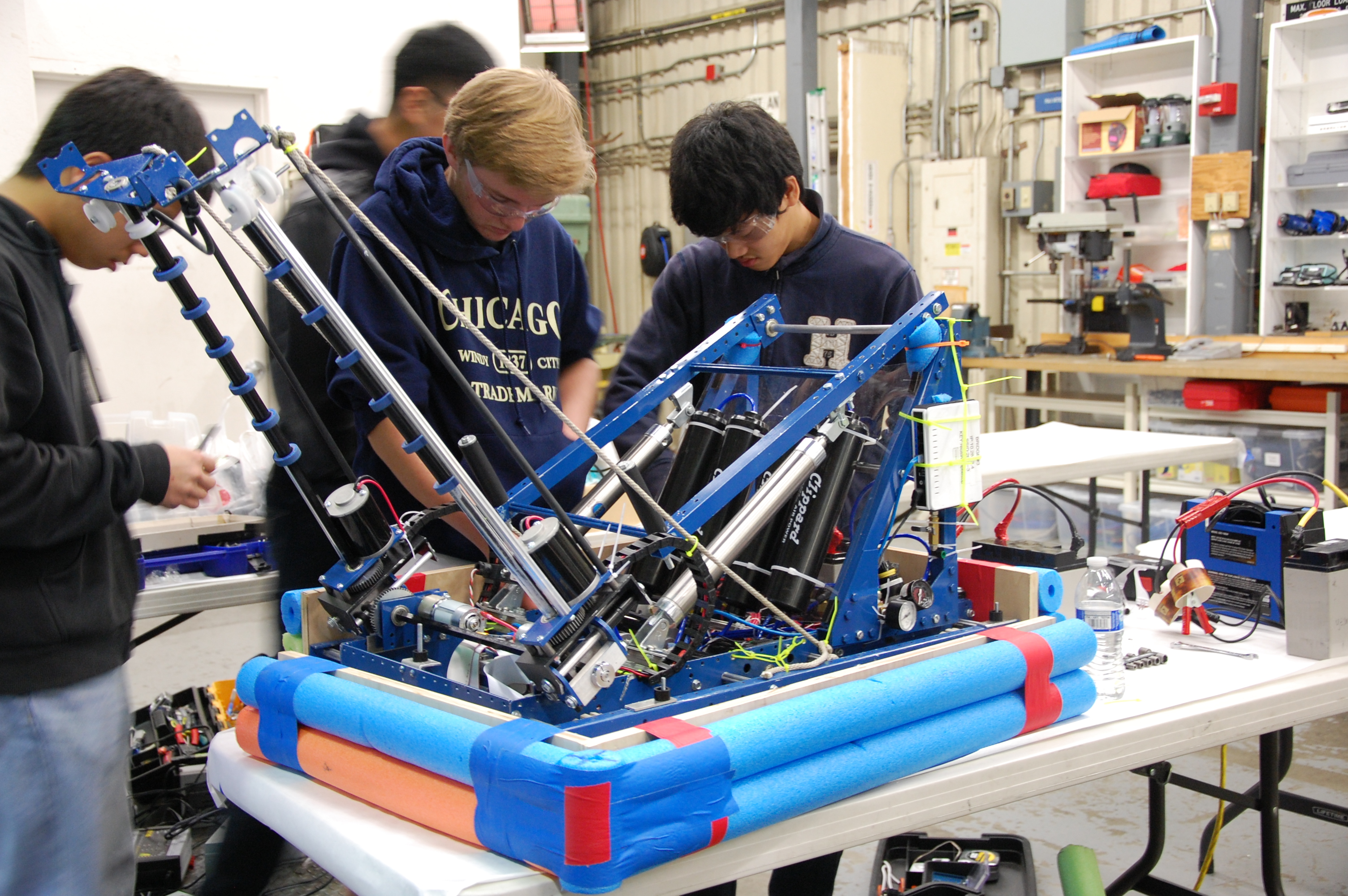
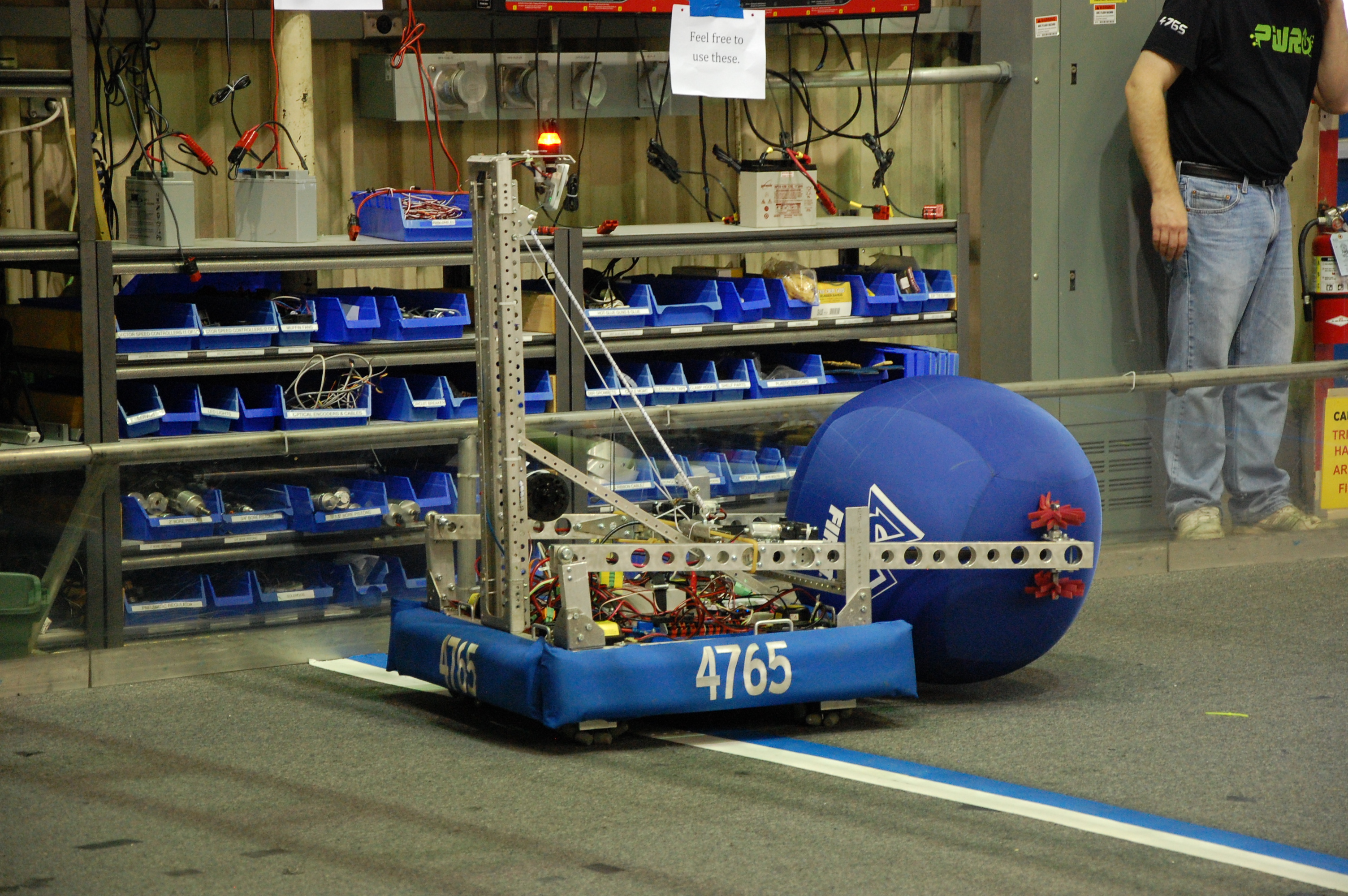
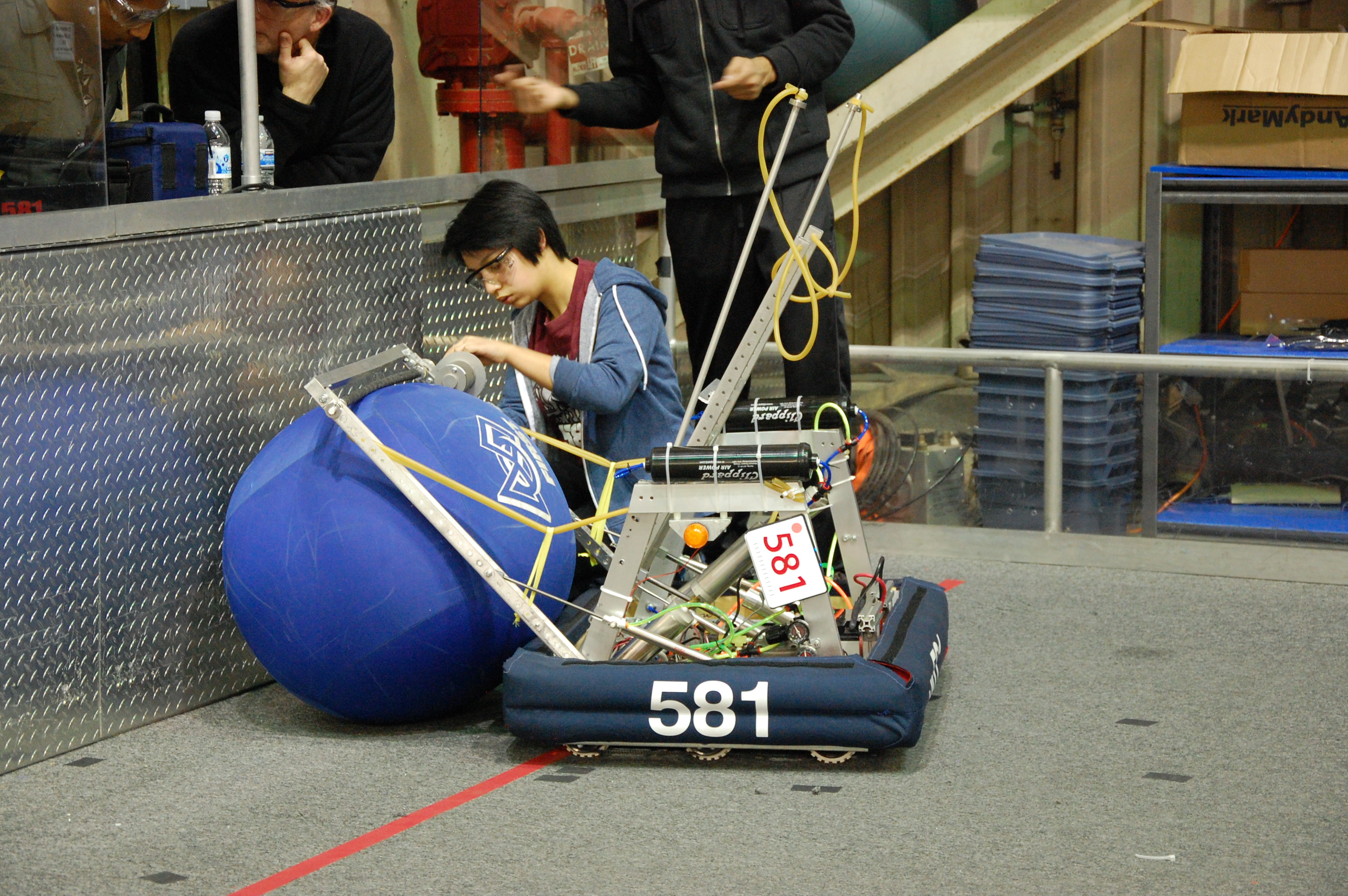
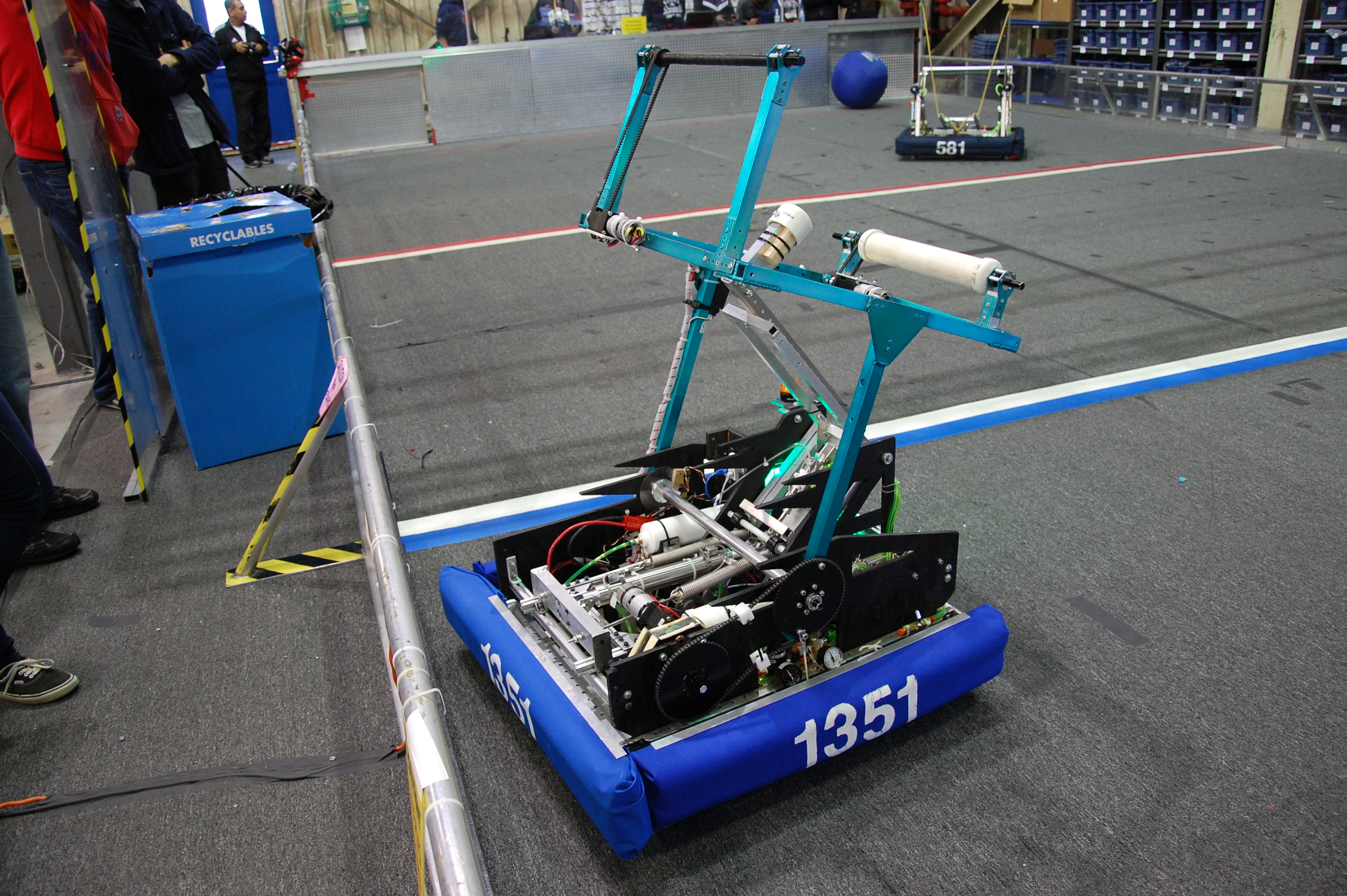
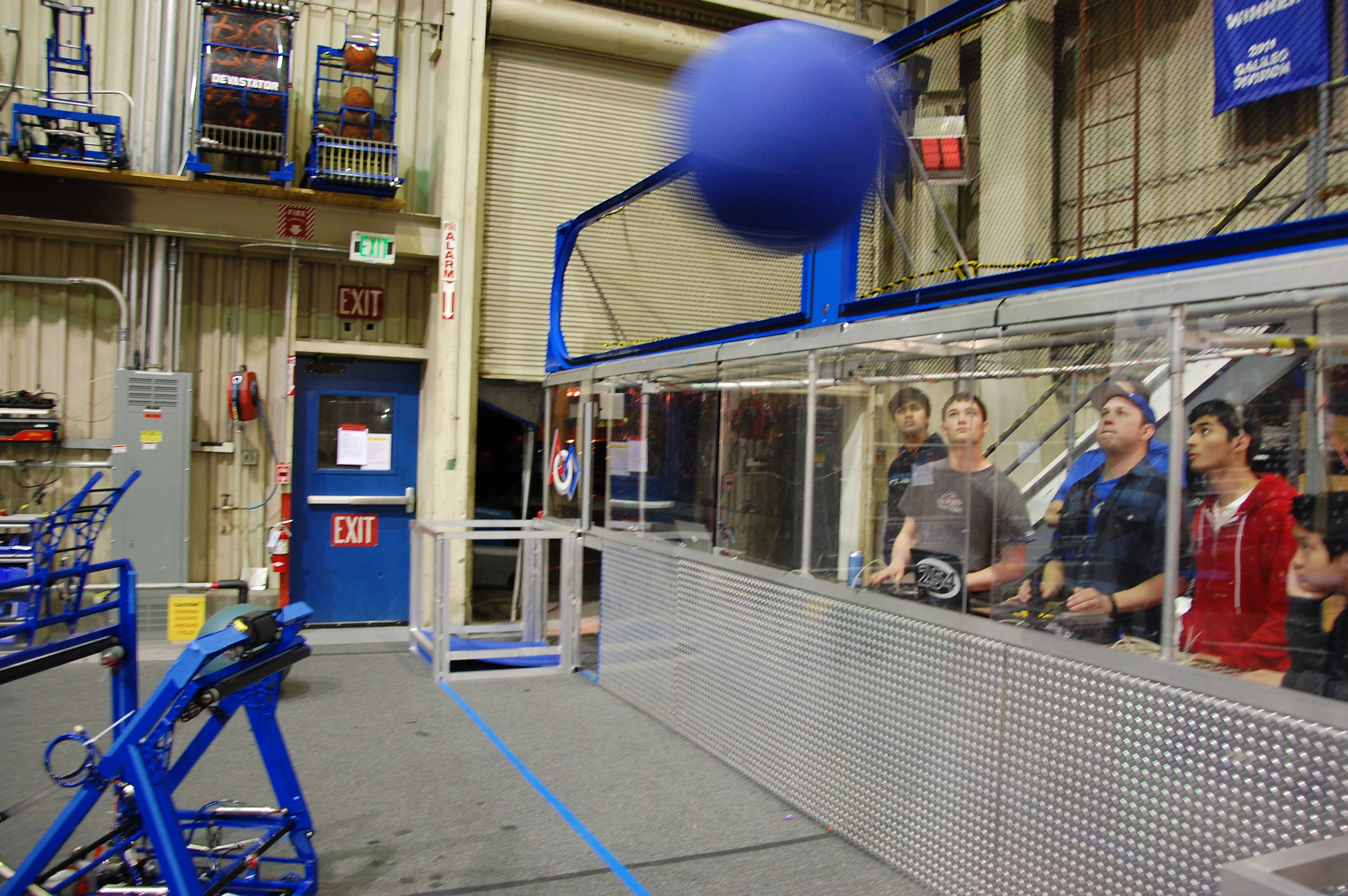
Team 604 (Quixilver), Team 192 (Gunn Robotics), Team 4765 (PWR up), Team 581 (Blazing Bulldogs), Team 1351 (TKO), Team 3501 (Firebird Robotics), Team 4990 (Gryphons), and Team 2813 (Gear Heads) all shared our lab today to practice on our almost full size field. Since most of the teams don’t have access to a field often (if at all), it allowed them to tune their robots so that they score, pass, catch, and move better.

Team 604Team 192Team 2813Team 4765Team 581Team 1351Team 3501Team 4990

Wiring and Assembly

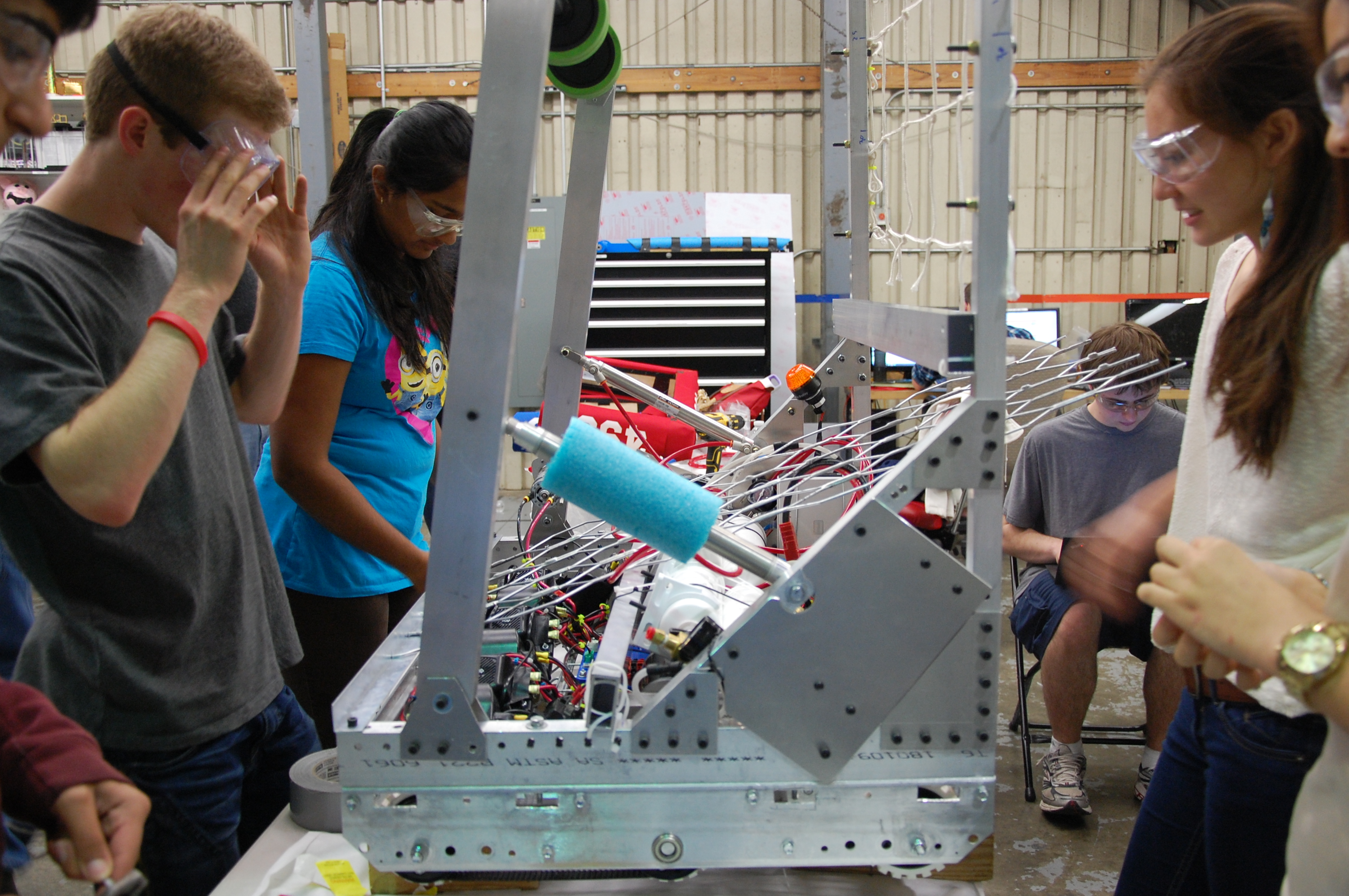
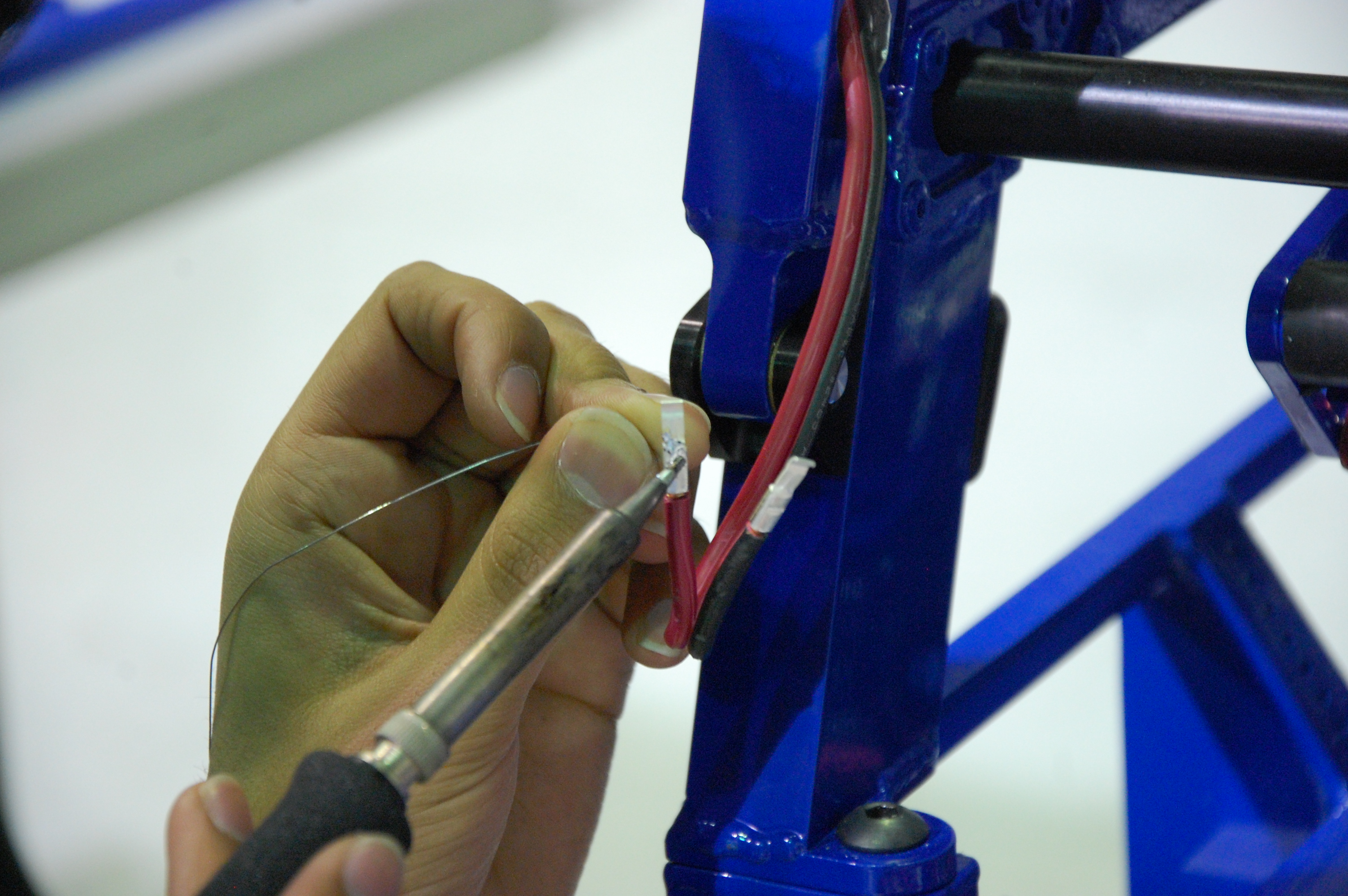
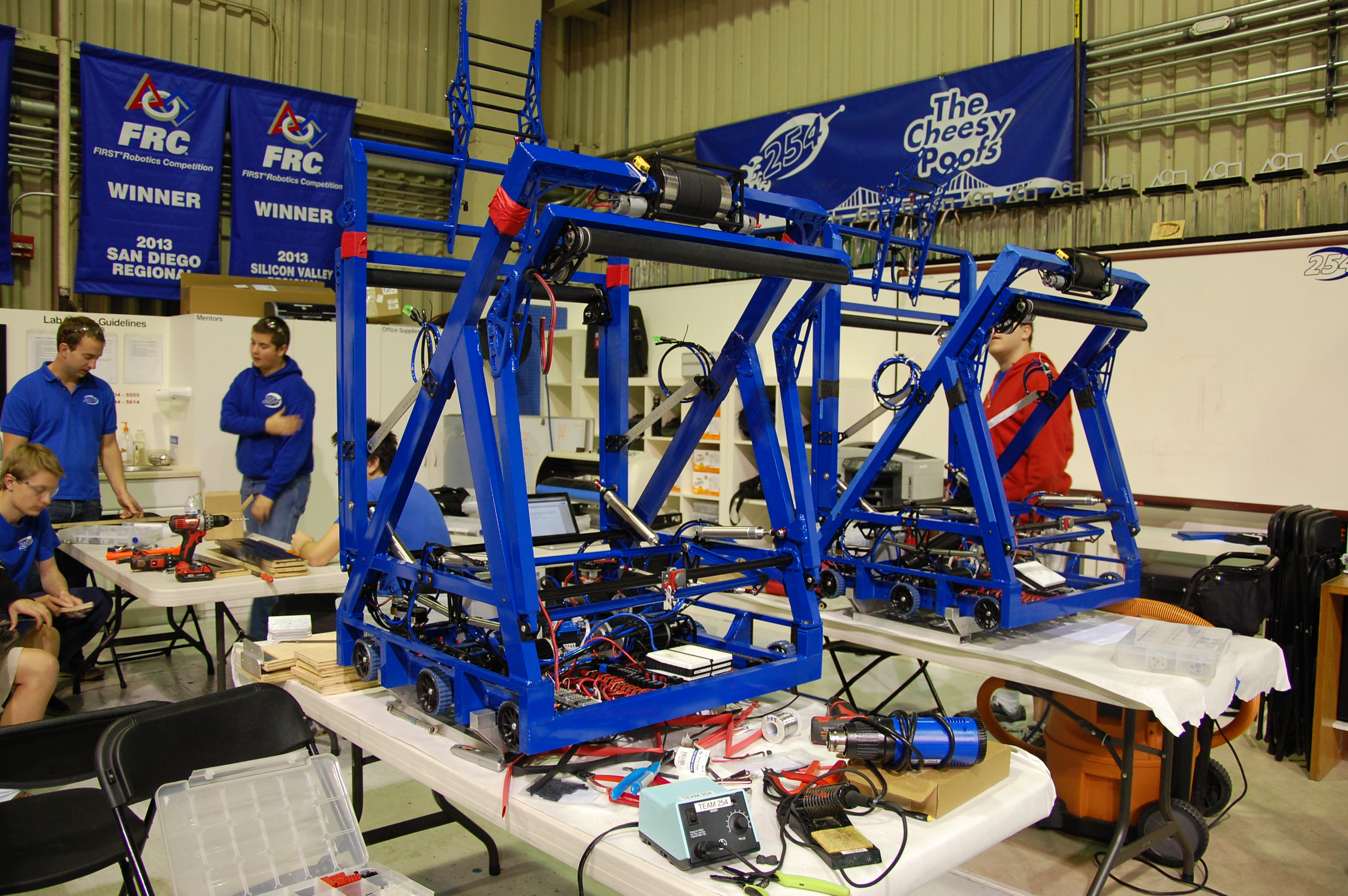
While the other teams were testing their robots, we were finishing the wiring on our practice and competition robots. Specifically, we were working on wiring bump sensors and Intakes. We also worked on finishing the hood. Aside from a couple of parts and wires, the robot is mostly built.

A student wiring the intakeThe two robotsA mentor inspecting the hood

Manufacturing

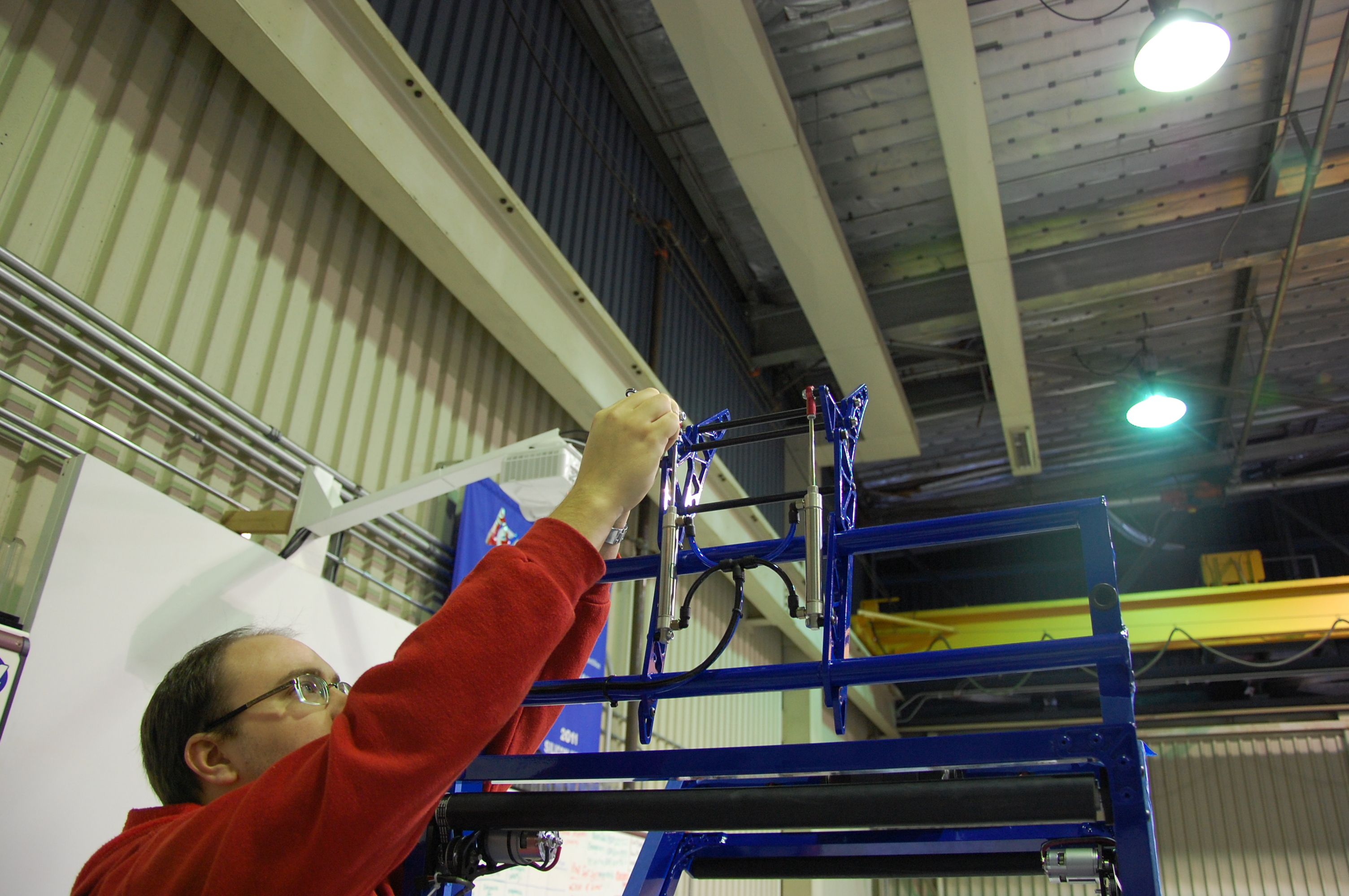
A Couple of our team members worked on manufacturing piston parts, and a couple of members worked on assembling the bumpers. The pistons that they are working on create a unique linkage between two pistons where one piston "locks" the other piston in place so that the rear intake can be locked up when shooting.

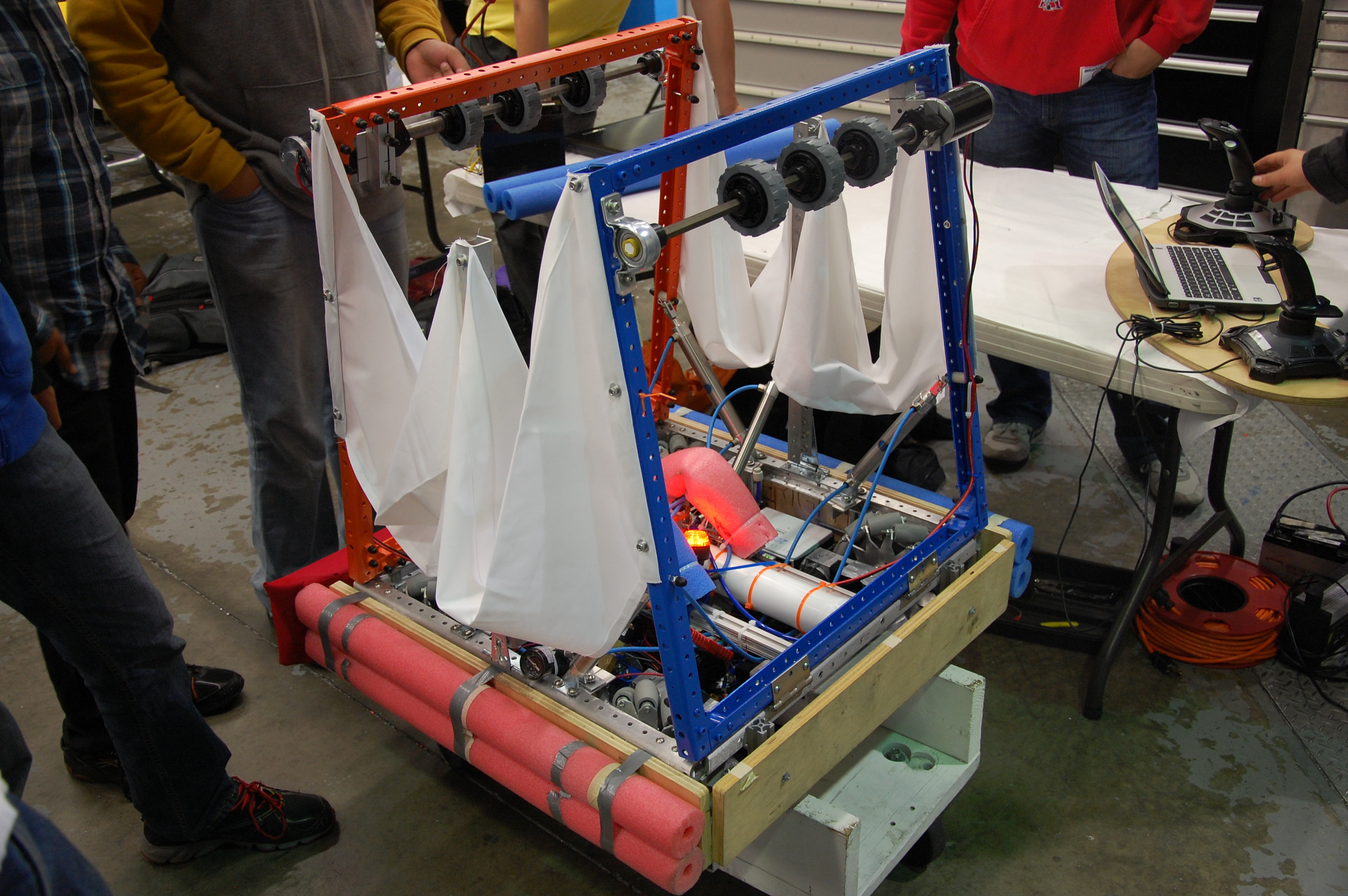
The bumper team started making two blue bumpers. Students affixed pool noodles along each side of the wood bumper frame with gaffers tape. Then, they stretched a full loop of cordura fabric around each bumper and stapled it down along the inside. Students took extra care to eliminate as many wrinkles as possible on the bumper fabric.

Shot Testing

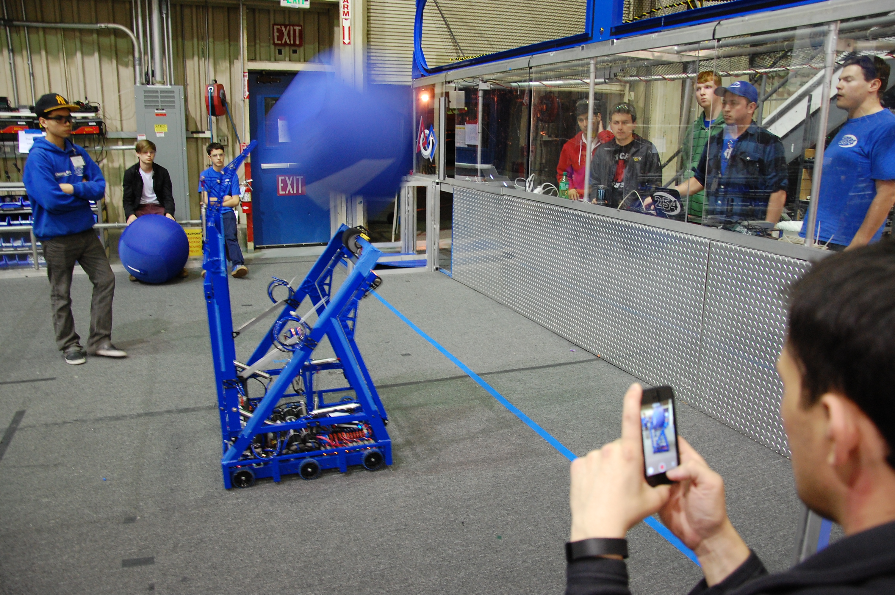
As students tested the robot shooter, they noticed that the ball was being impeded by something before it touched the shooter flywheel. Using a slow\-motion camera, they were able to observe the process of the clappers pushing the ball up the shooter. Programmers adjusted the timing of the clappers to push the ball up vertically. Then, they adjusted the power of the clapper pistons to optimize each shot.

Slow Motion Videos

Action Items

\- Finish Assembling Bumpers
- Finish Assembling the robot
- Make Robot Flyers
- Make the Robot Binder
- Program the robot

Taking her out for a spinEnjoying some quadcopter

Day 1: Kickoff and Game Analysis

2014 FRC Build SeasonFIRST Robotics#FRC Build Blog#prototyping

Kickoff Overview

Today kicks off the 2014 FRC Season for Team 254. The mentors and students are equally ecstatic for this year's challenge, Aerial Assist.

Google Drive PDF of the Game Manual:
https://drive.google.com/file/d/0B_TTQ23_FVkAWjM0cjBsbUw1TkU/edit?usp=sharing

Game Animation:

Team Kickoff

Today a group of students attended the 6:30 to 9:30 local San Jose kickoff at Morris Dailey Auditorium. A few others watched the NASA Live Stream from home. Subsequently, at 10, the team met for the team's kickoff event and discussed the plan for the coming six-week build season. The team then broke up into groups and discussed strategies in terms of necessary robot qualities, priority tasks, and possible scores. The parents and mentors simultaneously discussed logistics and the build plan in more detail until the student leaders returned to present their ideas to the entire group.

Game Analysis

Students and mentors discuss rules

After lunch, about 70 students congregated in the Bellarmine Robotics Lab to examine and better understand the team rules. In particular, they discussed the definitions of assist and possession and clarified the rules for such actions and others on the playing field. For the first two and a half hours, the group went through the relevant sections of the game manual and encouraged group discussion to find possible holes and list them to check with FIRST later. The group noticed some deviations in rules from previous years: the field is two feet narrower at 25 feet, and the match is 30 seconds longer. The autonomous period is five seconds shorter at 10 seconds, and the tele-operated period is 35 seconds longer at 2:20. Andrew Torrance noted the possible issues with battery life with the 25% longer match time. In addition to discussing rules, the team also formulated questions concerning the regulations to ask FIRST:

  • Can teams do assists in autonomous?
  • Can teams hold balls in autonomous to do an assist later?
  • Can a team throw over the truss again to try and get a catch, say, if an alliance earns a successful truss score, but does not successfully catch. Can the alliance try for a second chance? In other words, while the group recognizes that only one truss score counts per cycle, do the truss score and the associated catch score have to be earned on the first attempt?
  • Do teams get points (ex. throwing and catching in the end game) immediately, or do the teams only get them once the cycle completes? This is related to the question of assisting in autonomous. Possible answer: Maybe not because autonomous shots are not cycles.
  • Teams need clarification on which goalie zone to which the initial position regulations refer. In which goalie zone do teams start if they do not want to start in the white zone? Can human players help in the middle of assists?
  • Can human players catch truss scores to make them legal?
  • Teams need a better definition of possession for robots in general. For example, for a trough-like robot, is holding the ball as it rolls considered possession? What time period differentiates harmless "deflection" from "possession" of the opponent game object (which earns a severe technical foul penalty)

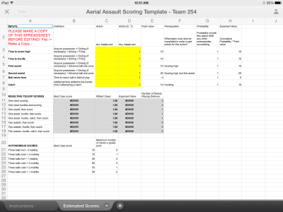
Jared's strategic model with numbersJared's strategic model with explanations

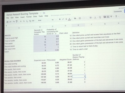
After a short break, the team's new mentor Jared set up a Google Spreadsheet that evaluated the effectiveness of certain "assist" strategies, with combinations of 1-3 assists, a truss "hurdle," and the truss "catch." He took student input for the point values corresponding to each action, the expected time taken for each action, and the probability of the action being carried out successfuly. He then calculated out a rough model of the weighted point values expected from strategies in the tele-operated mode of the match. The group was then able to analyze the efficiency of certain strategies. In the process of discussing strategies, the team also created two other strategy charts and lists (pictured).

Initial Strategic ModelPat's Strategic Model with Conclusions

Further Analysis and Prototyping

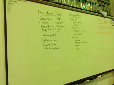
Discussion at NASA concerning field elements and prototyping

After dinner, approximately 20 students worked with the mentors to list some possible designs and to plan out the next week's prototyping schedule. The group prioritized the prototyping of possible modules, specifically shooter designs and catching mechanisms, with design input from students and advice from our experienced mentors. They also discussed what field elements were most necessary for prototyping for the next few weeks and listed them as well. Finally, they discussed the mathematics and physics of shooting a 25-inch, compressible, bulky, and irregular projectile into a 3-foot goal. For example, mentors noted that we might as well design a robot to shoot from farther away from the goal, since the shallower angle of entry would give greater allowance for error. Mentor Paul Ventimiglia also determined that giving the large exercise ball some backspin helped in precision, though it also required more energy to apply both linear force and rotational torque.

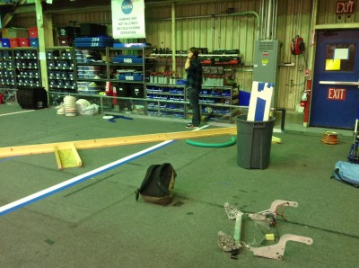
Goal in progress, to be mounted

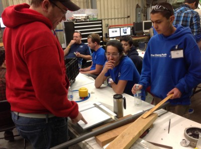
Tonight, we mainly focused on the building a preliminary goal with which to prototype before the field arrives and on prototyping and testing the effectiveness of a flywheel shooter and a slingshot shooter. Paul worked primarily with Godwin Vincent, James Holden, Jeremy Tanlimco, Vidur Maheshwari, Miggy Francisco, and Joncarlo Avila to design, sketch, and begin building a prototype for testing the effectiveness of a flywheel on such a large game object. They determined the best wheels with which to work based on their ability to grip the surface of the unusual game object. The prototype design was finalized and they plan to use four large wheels on the same axle hooked up to curved plywood "rims" to optimize the compression on the ball and somewhat minimize the size of the already bulky prototype. EJ Sabathia and Noah Marcel worked on the slingshot design, taping a 2013 Ultimate Ascent Frisbee to surgical tubing and hooking up the system to an alliance wall. The ball consistently bounced about 1/3 of the way down the court, given about 4 or 5 feet of backward stretch.

Paul sketches a design for and directs students in building the flywheel shooter prototype

Lab closing time: 11:00

Action Items

Translation: Future Work Opportunities for Members

  • Help Paul with the Flywheel Shooter design
  • Help EJ with Slingshot Shooter design
  • Help Nick Mercadante machine metal for prototypes
  • Ask mentors to begin and lead prototyping projects for other designs

Day #31: Field Assembly

2013 FRC Build SeasonFIRST Robotics#field#FRC#FRC Build Blog

Practice Field Assembly

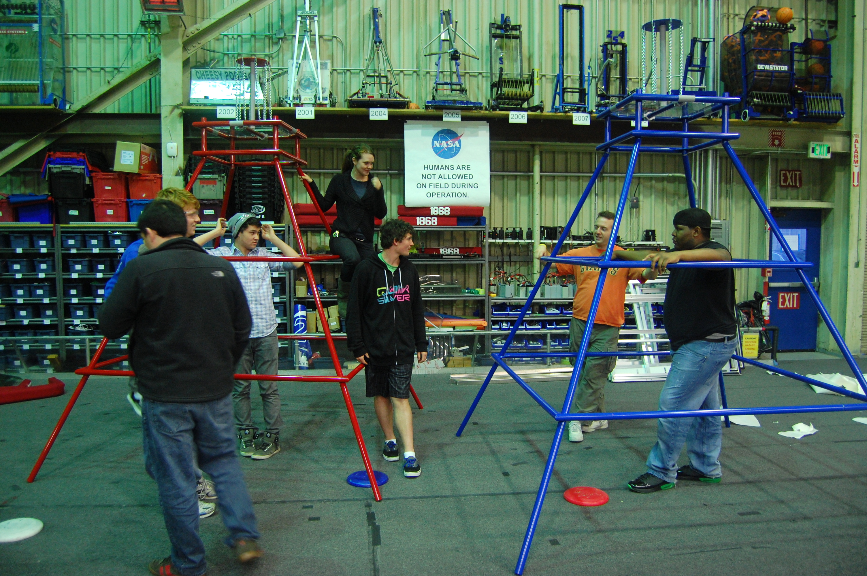
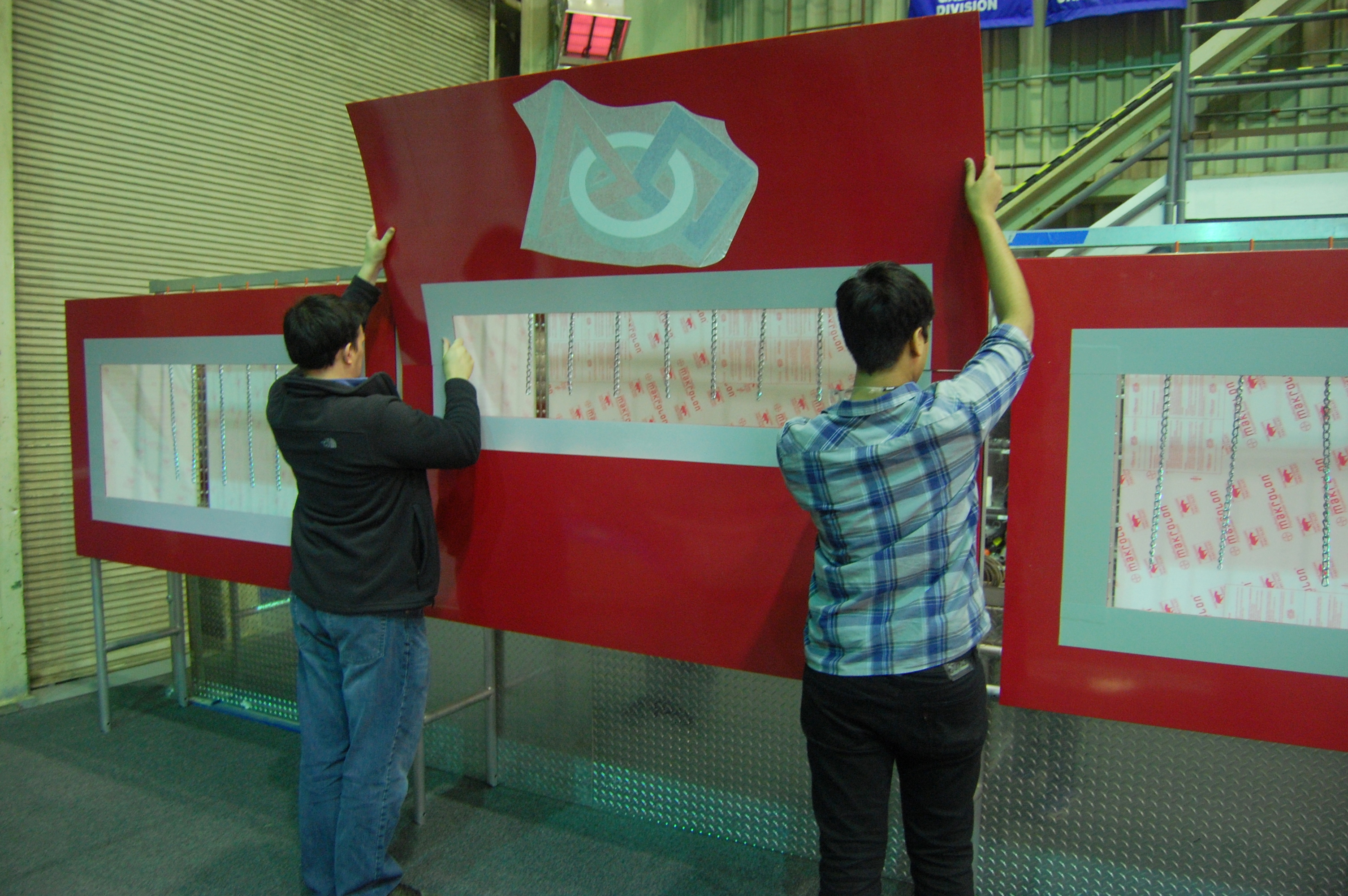
Without a doubt, the highlight of the day was the arrival of the official field pieces. Students spent much of the night organizing the many parts that arrived at the lab today and assembling the field elements themselves. The pyramids were the first objects completed, with both pyramids being fully assembled by around 6 pm. Between completion of the pyramids and dinnertime, students worked together to unpack and sort various field components, as well as cleaning up miscellaneous parts lying around in the lab to make way for the new arrivals. After dinner, the whole team got right back to work putting together the goals, the trusses they rest on, and the corner feeder stations and low goals. Due to size constraints, we will have only 2 of the 4 corner feeder stations, and the goals will need to be mounted in a unique way. The netting will be assembled at a later date. The field is very large, but also really unique and cool. We are excited to have the official setup and will begin practicing as soon our robot's shooter and climber are functional.

DSC_0351

DSC_0384


DSC_0359

Programming

Though the field assembly was the main job of the night, other tasks were being worked on as well. The programming team began the night by working on fixing the Cheesy Drive code to address the issues that had been discovered the night before. The deadband value of 0.1 was found to be too high, so it was reduced to 0.02, a value judged to be more reasonable given deadband values from prior years. An investigation is currently ongoing into what is causing a strange drive bug where rapidly switching from full forward throttle to full backward throttle causes the robot to exhibit unusual "jumpiness" while on low battery. Finally, work continued on finishing a graphing system for the Smart Dashboard.

CAD

Students and mentors continued work on finalizing the CAD. Currently the intake has been finalized, and the conveyer and shooter are close to being complete. The climbing mechanism position has been determined, but mounting is still being finalized.

Machining

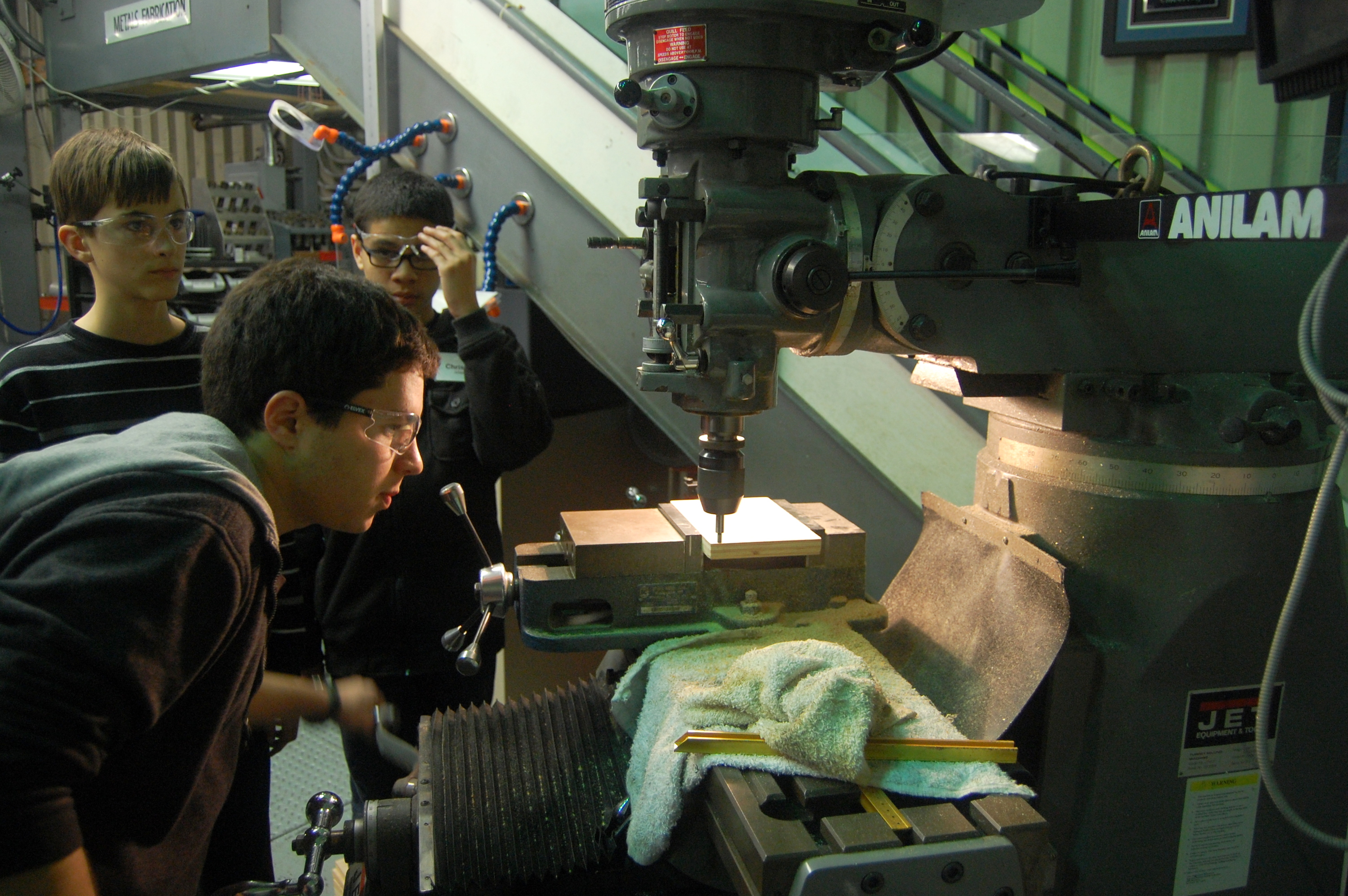
Students used the mill to make aluminum angles to mount the wooden bumper segments together. Once the wood segments are complete we can assemble the bumpers.

Students also used the lathe to make shafts with snap ring grooves for the conveyer. These will be used with the Polyurethane Tubes and mounted once we finish machining the rest of the superstructure.

DSC_0328

Action Items

  • Complete field assembly
  • Contnue investigation on Cheesy Drive
  • Finish grapher for Smart Dashboard
  • Continue machining parts for the superstructure
  • Finalize the CAD of the converyer, shooter, and climber

Day #5: Continued Prototyping

2013 FRC Build SeasonFIRST Robotics#FRC Build Blog

Today was a very productive day at the lab. There was a lot of progress made in many areas.

Prototyping

Shooter Prototype

Improvements were made to the shooter prototype. After students replaced a faulty CIM motor, an adjustable base was added to the linear shooter to allow testing at multiple angles. This base will help optimize the perfect angle for shooting a frisbee. The base was constructed out of kitbot parts and 80-20 extrusion.

D7K_3464

Richard assisting students with the adjustable shooter platform assembly

Intake Prototype

Students worked on improving the roller-intake prototype by testing different kinds of tread spinning at different speeds. It was found (unsurprisingly) that the roller must be spinning very quickly (about 2,000 RPM) to intake the frisbee. Long rough-top tread attached as "fingers" did not work well. A piece of rough-top tread that was wrapped around the roller worked the best.

After determining this improved treading configuration, students and mentors worked on setting up the prototype as an over-the-bumper intake. Rather than sucking-in the frisbee horizontally, tests were conducted to see if the frisbee could make a smooth and easy transition from a horizontal position on the ground to an angled position over the bumper.

D7K_3465

Updated Intake prototype

Restoring the 2010 drivebase

Students continued to attempt to restore the 2010 drive base, in order to attach prototypes and drive around. After an hour of debugging, it was concluded that a faulty cRIO was on the robot. The efforts were abandoned because of a lack of replacement cRIO. Hopefully, a new cRIO is acquired soon in order to continue testing.

Restoring the drivebase was also supposed to be an excercise for the new programmers, so they could practice writing brand new code and uploading it to a functioning robot.

Programming

Tom dropped some knowledge bombs on the programmers today.

Constants


Students continued to brainstorm and discuss possible ways of updating values without having to re-compile or re-deploy the code.  Some ideas that was brought up was having a text file for each constant, or having an "isModified" boolean value somewhere.
 

Action Item List


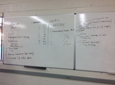
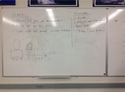
An action item specific to programming was created yesterday.  This is essentially a to-do list, which organizes and tracks tasks what need to be completed and the priorities of tasks.  This list should make it easier for students at the lab to more easily contribute to programming effort.


Miscellaneous

Light Control Box

Two students worked on modeling a project box and the components to go inside it. This project box will house a power supply and will be the control box for the lights hanging on the trussing in the pit area.

image

Pit Area trussing for banners, lighting, and monitor mounting

D7K_3466

A student modeling the project box in SolidWorks.

Action Items for Tomorrow

  • Fix the wiring to the cRIO on the 2010 robot; flash new image to cRIO

  • Work on and test prototype for intake

  • Work on and test linear shooter prototype

  • Complete drivetrain design. Deadline is Friday.

Lab closing time was 11:00 pm

Day #4: Success with Intake and Shooter!

2013 FRC Build SeasonFIRST Robotics#FRC Build Blog

Today was a huge improvement in student attendance over yesterday. With our first active weekday build, a majority of the time was spent designing and beginning initial prototyping of an intake mechanism.

Prototyping

Intake Prototype

Students worked in a group to brainstorm ideas for an intake mechanism that will allow the robot to take in discs from the ground.  One of the several ideas brought up include horizontal rollers to roll the discs in.  However, the orientation of the disc (facing upwards or downwards) and friction between the carpet and the disc are challenges.  Currently, one new intake prototype has been constructed that can take in discs on the ground from either orientation. 

intake

Students brainstorming ideas for the intake

Shooter Prototype

Additionally, some students are continuing work on manufacturing parts for shooter prototypes.  

One new shooter prototype that is under construction is a linear shooter, powered by two wheels.  One wheel will be powered such that it is faster than the other.


manufacturing

Manufacturing parts to build a shooter prototype

Testing Prototypes

Some students are using the drivebase of the 2010 robot, Onslaught, in order to test shooting and future intake prototypes.  Currently, there is a problem with power to the cRIO, which prevents controlling or deploying code to the robot.  Once the 2010 robot is up and running, the team will attach prototypes to the robot to test out prototypes on the field, while driving.


onslaught

Drivebase of the 2010 robot, Onslaught

Programming

Reading Constants

The programmers discovered that original idea to use Java reflection will not work because the robot uses Java ME (mobile edition), which does not support this feature. They brainstormed some other possible solutions including using a hash map for storing variables read from a file, but it is likely unfeasible due to its heavy computational expense. Another idea is to use a flat text file with constant values that can be transferred to the robot without re-compiling and re-deploying code. 
Controls

In addition, the programming team tested out a Logitech game controller as a way of driving the robot.  The analog sticks on the controller were successfully used to control the drive.  More comparisons and tests between joysticks and the game controller will occur later on in the season.
Action Items for Tomorrow

  • Fix the wiring to the cRIO on the 2010 robot; flash new image to cRIO

  • Work on and test prototype for intake

  • Work on and test linear shooter prototype

Lab closing time for the night was 12:30am

Day #2: Finished Pyramid!

2013 FRC Build SeasonFIRST Robotics#FRC Build Blog

Today the team got a great start as soon as we could access the lab, making substantial progress on a multitude of projects.

Prototyping

Today in prototyping the team pursued our 3 designs decided yesterday for shooting mechanisms which are:

  • Radius design

    • Continued to try and make shots using the pneumatic air wrench to

      drive the flywheel

    • Used the strategy of touching the pyramid to take shots without being hit by opponent robots

    • Created a feeding device to automatically load frisbees into the shooter


Radial shooter

  • Linear Design

    • CNC machined part of the belt mechanism to create a tensioned timing belt system to launch the frisbee

    • Added guide rails to create a solid static wall opposing the timing belt to create spin on the frisbee

    • Added flanges to the pulleys to help guide the timing belts

    • The pulleys are powered by a direct mounted CIM Motor running at 5300 RPM

    • Shows promising capabilities both in power and spin and is being pursued in greater depthLinear

  • Arm Design

    • Completed initial prototype design

    • Mechanism is powered by a 1 stroke piston

    • Semi-effective at short range

    • Needs to be modified to increase range and spin to be able to get a better understanding of its capabilitiesFlinger

Design

The decision was made to build a modified version of the 2011 drive system which operated a 6 Wheel Drivetrain System with two speed gearboxes (high gear at 19.8fps, low gear at 7fps). Center wheels are lowered to allow for maximum maneuverability. 3.5″ wheels keep the robot center of gravity very low to the ground. Additional design improvements have been pushed to tomorrow for final decisions. The team is still in the process of brainstorming designs for both intake and climbing/hanging mechanisms.

Gearbox

The part drawings for the main shafts in our drivetrain are completed and ready to be sent out to sponsors. The completed drawings are for the following parts:

  • Drive Gearbox Output Shaft

  • Drive Gearbox Intermediate Shaft

  • Wheel Shaft Medium

  • Wheel Shaft Short

Screen Shot 2013-01-07 at 10.45.25 AM

Output shaft drawing


Field Construction

Students completed all components and assembly of the pyramid, creating a solid basis for hanging prototype testing.

sketchpyramid

Machining

The CNC mill was used to mill components for the linear shooter prototype and is prepared to be in around-the-clock machining as soon as the preliminary metal shipment has arrived.

Programming

The programmers began to write some code in Java to deploy to the 2012 robot. They used the CommandBasedRobot structure for the code, and fixed all previous errors that popped up before during deployment.  The code was deployed and ran successfully. Currently, the team has a completed drive subsystem and a couple drive commands.  In addition, some students worked on a system to read values from a file for on-the-go constants editing.

 Lab closing time for the night was at  1:00am