522 posts

Ball Launcher Prototyping

2010 Teams 254/968 Collaborative Build Blog

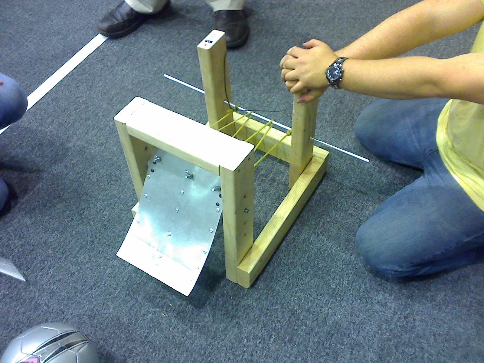
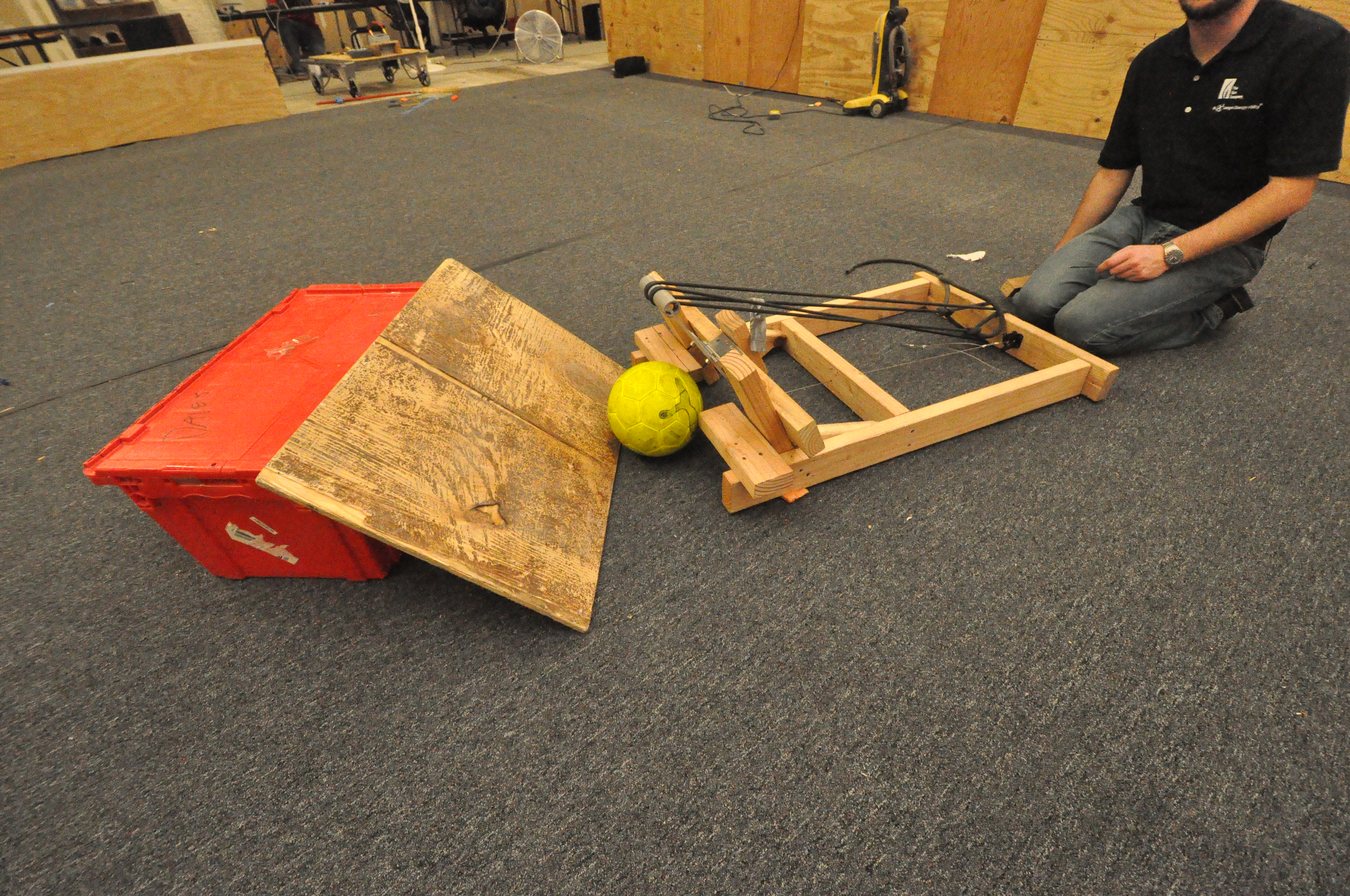
Earlier today, RAWC students and mentors brainstormed ideas while at the high school, coming up with a few mechanisms to launch a soccer ball.  A few of those ideas were actually plausable(we went forward with one).  We built a launcher frame that takes into account the size restrictions placed on teams(Ball can only be 3" inside the 'bot, Launcher mechanism can only protrude 2", Ball must stay in contact with the floor).

Here's a photo of the launcher.
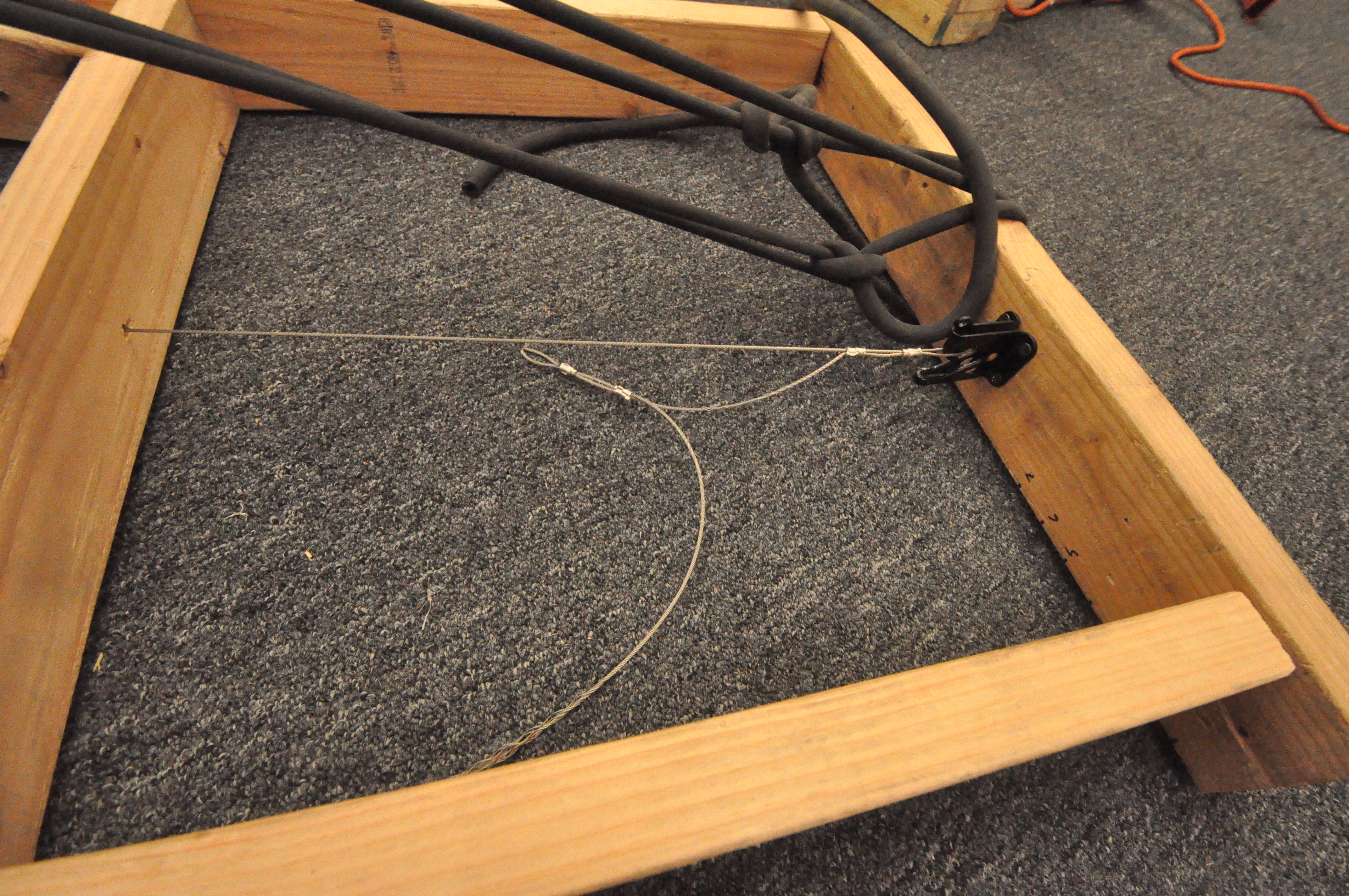
Here's the release mechanism:
Here are a few videos:

Long Range (Corner to Corner) Preset Test. This test was setup having the launcher's frame(the size of the 2009 base) touching the wall of an alliance station. The frame was also pointed toward the opposite corner(diagonally). After launching the soccer ball using the long range setting, the ball landed approximately 2 feet away from the opposing alliance's home zone.

Original video unavailable.

Mid Range (Corner to Corner) Preset. This test was setup having the launcher's frame(the size of the 2009 base) touching the wall of an alliance station. The frame was also pointed toward the opposite corner(diagonally). After launching the soccer ball using the mid-range setting, the ball landed close to the midfield divider.

Original video unavailable.

Ramp Contact Testing. This test was configured in a way that a KOP tote was placed in varying distances from the front of the soccer ball. We tested the following scenarios: Tote 4FT from ball(long range), Tote 4FT from ball(mid range), Tote 2FT from ball(long range). During our testing, we determined that the ball does not come close to touching the tote in all of the configurations. We performed one additional test that was not documented; the tote was placed 2FT from the ball and the launcher was set into the mid range position. The ball clearly comes in contact with the tote, altering the trajectory of the object.

Original video unavailable.

Additional ramp contact testing. These videos include a plane that is angled to a 45 degree slope. In addition, the ball is in contact with the inclined plane. This test was to demonstrate the launcher's capability to launch a soccer ball accurately in the case that it was touching the ramp.

Original video unavailable.

Angled ramp contact testing. This test is to demonstrate the effects of using our launcher while being offset from the ramp.

Original video unavailable.
Build Day 5

2010 Teams 254/968 Collaborative Build Blog

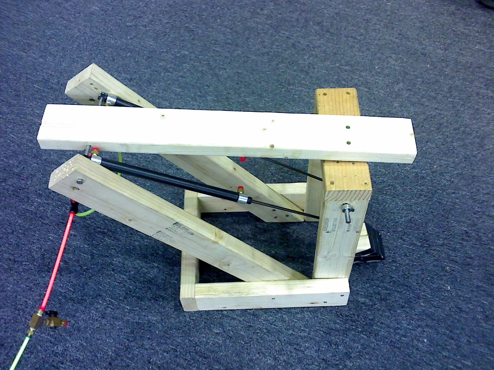
Today at the Nasa lab we had roughly 12 students experimenting with various prototypes for kicking/launching mechanisms. One group seemed to find particular success with a pneumatic-kicker, which was able to launch the ball just over the hump attaining a distance of about 15 ft.

The girl scouts also came up with an interesting concept of a surgical-tubing powered scoop. This design may be promising, but has not been sufficiently tested yet.

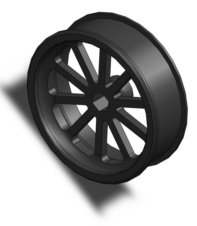
Meanwhile the design team worked diligently upstairs properly tolerancing the gearbox and shafts as well as designing the 4" wheels (see previous post).

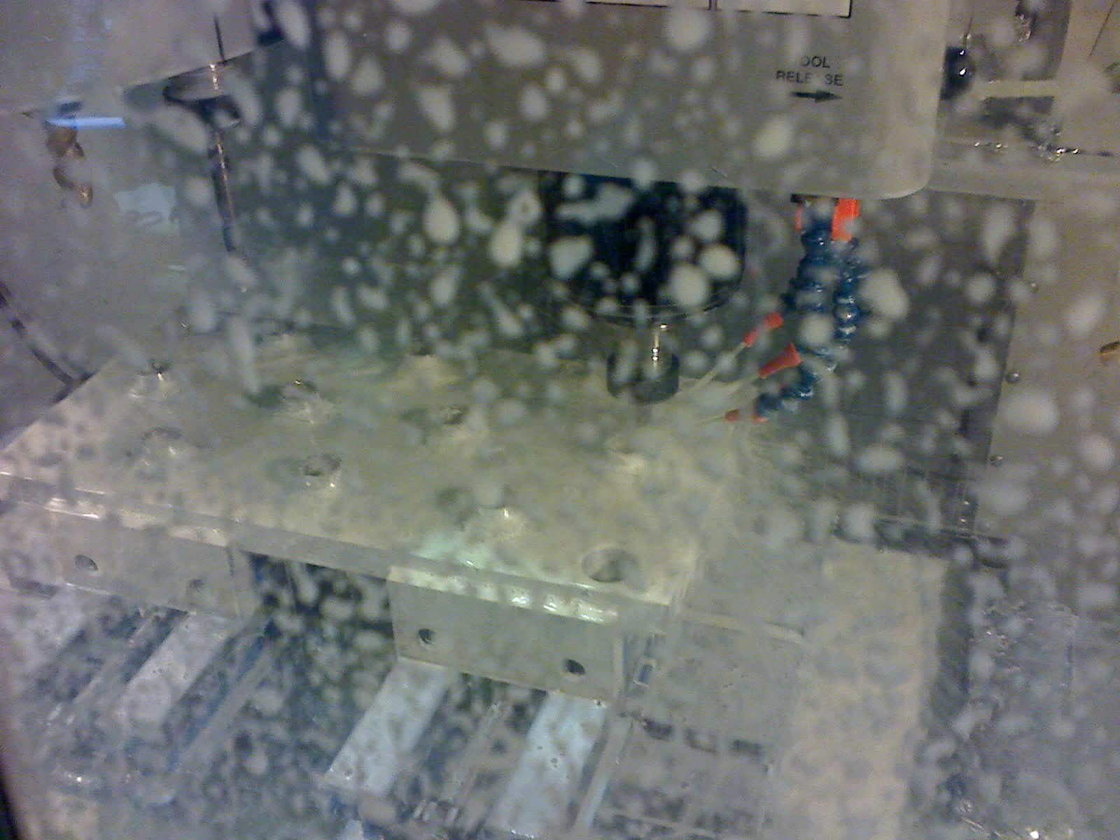
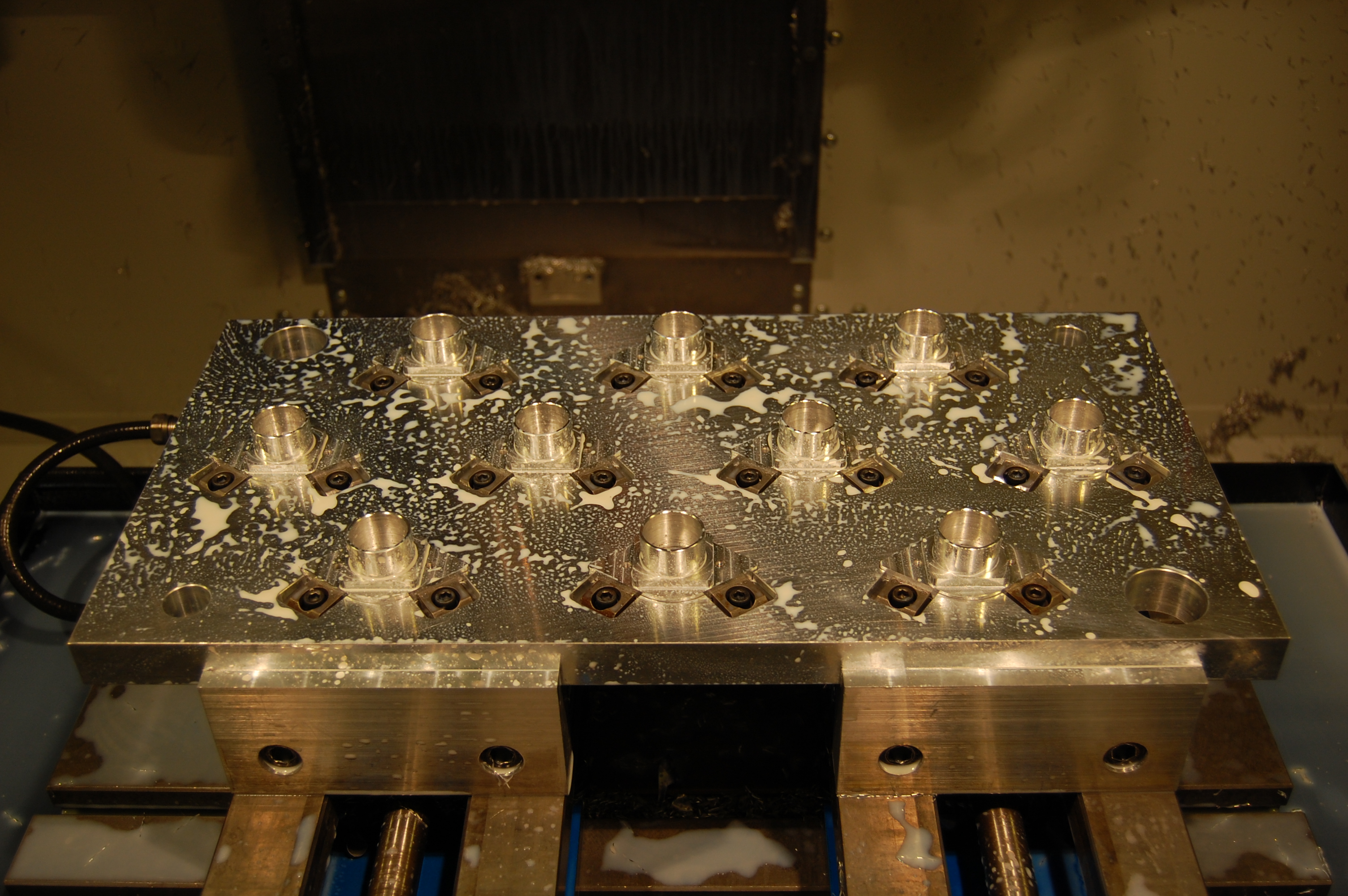
In the machine shop the CNC began rolling out the bearing blocks, doing the second pass.  By the end of tomorrow the bearing blocks should be ready for anodizing (provided there are no unseen complications).

Tomorrow the material for the wheels needs to be cut out so they are ready for machining. Pushing or launching the ball past the ramp has proved difficult, requiring excessive propulsion or front-spin and we will continue prototyping different designs.

Build Day 4

2010 Teams 254/968 Collaborative Build Blog

At Team 254's lab today, we had an extremely large number of people working hard to complete some common objectives.

In the manufacturing department, several students continued cutting stock for the bearing blocks.  Many of the bearing blocks have already completed their primary operation on the CNC mill.

In the design department, a very large group of students worked downstairs all afternoon to continue to develop prototypes for ball launching devices.  Some have been modified and improved to be tremendously more powerful than their previous states.  Upstairs in the CAD department, a small group worked hard all afternoon to CAD the Drive Gearbox.  As of 10:00 PM, the gearbox shafts are mostly done, but still need to be toleranced, which will be completed tonight to finalize the shaft drawings.  In the morning, the drawings will be sent to 968 and Pacific Precision for the shafts to be completed this week.

This week, the design team will finalize the gearbox and design the drive wheels so that the gearbox plates can be manufactured by Team 233 in Florida.  The manufacturing department will continue to manufacture the bearing blocks and will move on to the wheels once the bearing blocks are completed.

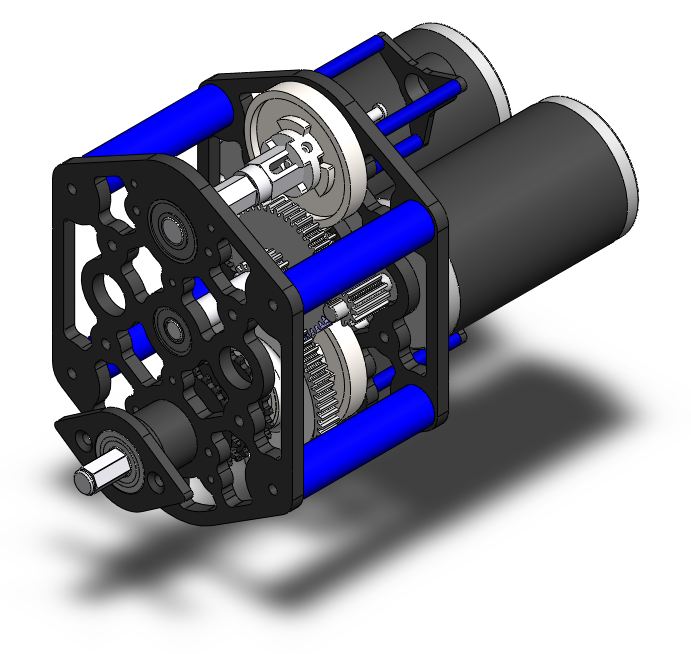
Final Ratios & Gearbox Info

2010 Teams 254/968 Collaborative Build Blog

Agreed Upon Specs:

2 Speed with Power-Take-Off (PTO) for Winch

4 CIM motors, 2 per side

Initial Reduction - 12:45

High Speed Reduction - 30:48  gives ~15.5 fps at 93% efficiency

Low Speed Reduction - 14:64 gives ~ 5.5 fps at 93% efficiency

All gears are AndyMark except for the 64 tooth dogged gear, 45 tooth intermediate gear, and the 30 tooth internediate gear, all of which are standard Martin gears.

The PTO shaft sits above the intermediate shaft and has one speed, and an the option for two with the addition of another three position piston.  We also have the option of disengaging the output to the wheels if we use another three position piston.

Options Clarified:

1. Wheels move when winch is engaged - two standard pistons required per gearbox

2. Wheels do not spin when winch is engaged - one standard piston, one three position piston

3. Wheels spin when winch is engaged, but winch now has 2 speeds - one standard piston, one three position piston

4. Wheels do not spin when winch is engaged, and winch has 2 speeds - two three position pistons

The cost of the three position pistons is ~$70.  The cost for the standard piston is ~$20.  The gearbox will be designed to accommodate any of these options without the need to change ratios, plates, shafts, etc.

Build Day 1 Meeting Minutes

2010 Teams 254/968 Collaborative Build Blog
  • Ideal design would utilize a  rigid 6 wheel / 8 wheel structure
  • Ideal design would also incorporate a mechanism that will allow the robot to traverse over bumps quickly
  • Both teams are wondering on the usage of 8" inch wheels. (Additional gearing)
  • Recommended Protyping: Build 6" wheel chassis on 6 wh/8 wh base
  • Didn't discuss ball manipulation mechanism
  • Winching should be relatively easy
  • The transmission should be the most important part of this game
  • 254 disagrees to lifting up two other robots(Reasoning: 50 lbs of parts for 6 points)
  • 254 recommends that we should winch ourselves
  • 254 will test 8" and 6" diameter wheels on 06 bot.
  • 968 will do CAD on wheel base distance with various wheels and distance from center to center.